| Tweet |

Custom Search
|
|

|
||
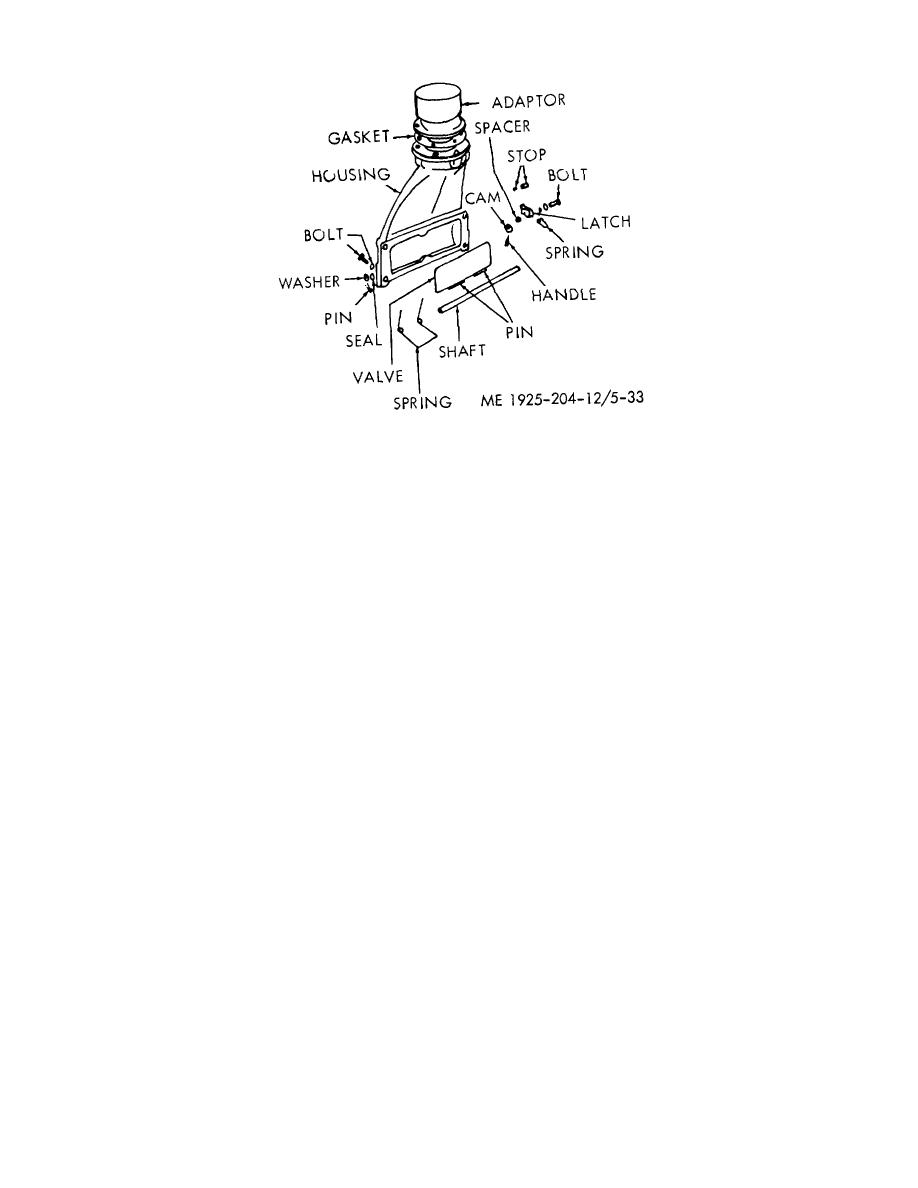
 Figure 5-53. Typical air shutdown (inlet) housing
(2) Remove the pins that secure the shutdown
b. Removal.
valve to the shaft.
(1) Remove governor from engine and blower.
(3) Note the position of the air shutdown spring
(2) Remove air cleaner and air inlet housing.
and the valve (for reassembly); then, withdraw the shaft from
(3) Remove eight bolts and lockwashers that hold
the housing to release the valve and spring in the housing.
engine front cover to the blower.
Remove seal from the housing.
(4) Remove air box drain tube clip and tube.
(4) Remove the bolt, lockwasher and plain washer
(5) Remove the 12 bolts and lockwashers which
from housing and remove the latch, latch spring, and spacer.
secure the blower assembly to the cylinder block. Remove
d. Cleaning, Inspection, and Repair.
the special 7/16-14 x 7 3/4-inch bolt from center of blower
(1) Clean all of the parts thoroughly, including the
front end plate.
blower screen, with fuel oil, and dry with compressed air.
(6) Move the blower assembly slightly aft to free
(2) Inspect the parts for wear or damage. The
the gasket between gear cover and blower end plate; then
face of the shutdown valve must be perfectly flat to assure a
remove the blower from the cylinder block.
tight seal when it is in the shutdown position.
c. Cleaning, Inspection, and Repair.
e. Reassembly. Assemble by reversing the procedure
(1) Inspect blower rotors. Minor abrasions on
in c. above.
surface of rotor lobes can be removed. However, if deep
marks are noted, replace blower assembly.
f. Installation.
Install by reversing the removal
(2) If there is rubbing and scoring between crowns
procedure in b. above; then tighten capscrews to a torque of
of rotor lobes and mating rotor lobes, replace blower
16-20 ft lbs.
assembly.
(3) Check blower rotors for excessive oil as this
5-19.
Blower
will indicate leaky seals and necessitate replacement of
a. General. The blower designed for efficient diesel
blower assembly.
operation, supplies the fresh air needed for combustion and
d. Installation.
scavenging. Its operation is similar to that of a gear type oil
(1) Fasten a new gasket to cylinder block at
pump. Two hollow rotors, each with three lobes, revolve with
blower pad with shellac.
very close clearance in a housing bolted to the side of the
(2) Place blower on cylinder block locating flange
engine. The rotor lobes are made with a twisted or helical
and start long bolt through hole in front end plate. Do not
form, to provide uniform and continuous displacement of air.
tighten this bolt.
(3) Install 12 bolts which hold blower assembly to
cylinder block and tighten to 50 foot-pounds.
5-67
|
||
 |
||