| Tweet |

Custom Search
|
|

|
||
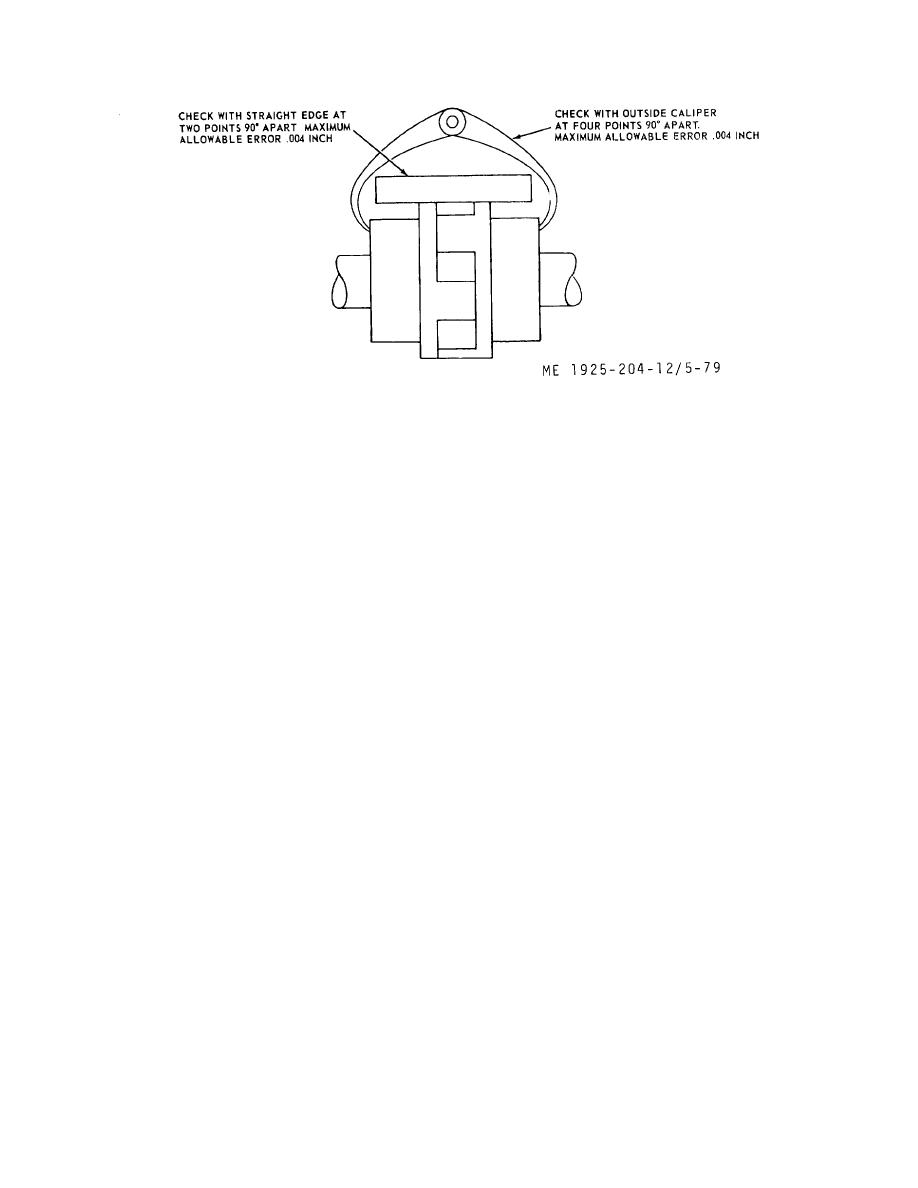
 Figure 5-79. Checking coupling alignment.
(5)
Remove drive endbell mounting bolts, tap
CAUTION
endbell loose from field frame and carefully withdraw
Do not operate pump until alignment
armature from field frame.
tolerances are met.
(6)
Remove capscrews from drive end bearing cap
and pull hearing cap from armature shaft.
5-43. Motor
(7)
Carefully pull drive endbell from armature shaft.
a. Maintenance and Adjustment (TM 55-506 ).
(8)
If brush holders are to be replaced, loosen
(1)
Lubricate in accordance with applicable
clamping screw and pull brush holder from mounting studs.
lubrication order.
(9)
Remove locknut and lockwasher from each end
(2)
Inspect brushes; replace brushes worn to one-
of armature shaft.
half normal length.
(10) Pull ball bearings from armature shaft; remove
(3)
Check brush tension; adjust tension to
inner bearing caps from armature shaft.
approximately 2 psi of brush contact surface.
d. Cleaning and Inspection (TM 55-506 ).
(4)
Inspect commutator; clean dirty commutator
(1)
Wipe parts clean with dry cleaning solvent in
with 00 sandpaper.
conformance to FED SPEC P-D-680.
b. Removal.
(2)
Inspect armature and field windings for damaged
(1)
Disconnect electrical connections from motor,
insulation. If insulation is defective, replace motor.
and remove cable from motor connection box.
(3)
Inspect brush holders for damage. Replace
(2)
Remove four mounting bolts, and slide motor
defective brush holders.
away from pump until clutch jaws are disengaged. Lift motor
(4)
Check brush tensioning springs; replace springs
from mounting.
that are broken or have lost tension.
c. Disassembly.
(5)
Inspect commutator for grooving, burning, or
(1)
Remove brushes from brush holders; mark
high mica. If defects cannot be repaired by taking a light cut
electrical connections to brush rigging for replacement upon
in a lathe, or undercutting, replace the motor.
assembly, and disconnect electric connections from brush
(6)
Rotate bearings by hand; replace bearings that
rigging.
bind or catch.
(2)
Pull coupling from motor armature shaft.;
e. Assembly.
remove key from shaft.
(1)
The order of assembly is the reverse of the order
(3)
Remove capscrews from commutator end
of disassembly.
bearing cap and pull bearing cap from armature shaft.
(4)
Remove commutator endbell mounting bolts, tap
endbell loose from field frame, and carefully withdraw endbell
from armature shaft.
5-107
|
||
 |
||