| Tweet |

Custom Search
|
|

|
||
 TM 55-1925-273-10-1
0043 00
CONTROL AIR RECEIVER
1
2
25 30 35
40
20
15
45
10
50
5
55
0
60
3
4
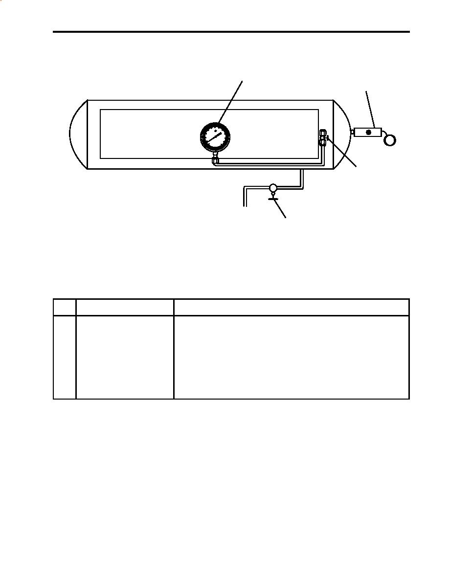
Figure 3. Control Air Receiver
Table 3. Control Air Receiver (refer to figure 3)
Key
Control/Indicator
Function
1
Control Air Pressure Gauge
This gauge indicates the pressure in the control air receiver.
2
Relief Valve
This valve opens to prevent over pressurization of the receiver.
3
Cutoff Valve, Control Air
This gauge secures the pressure to the control air pressure gauge.
Pressure Gauge
4
Drain Valve
This valve permits draining of condensate from the receiver.
0043 00-7
|
||
 |
||