| Tweet |

Custom Search
|
|

|
||
 TM 55-1925-273-10-1
0070 00
11. Set both motor controllers' ON-OFF switches (figure 5, item 2) to ON.
12. Ensure that the POWER AVAILABLE light (figure 5, item 3) is illuminated on both motor controllers.
13. Ensure that the MOTOR RUN light (figure 5, item4) is illuminated on both motor controllers.
ACTIVATE SHIP'S SERVICE AIR SYSTEM
1.
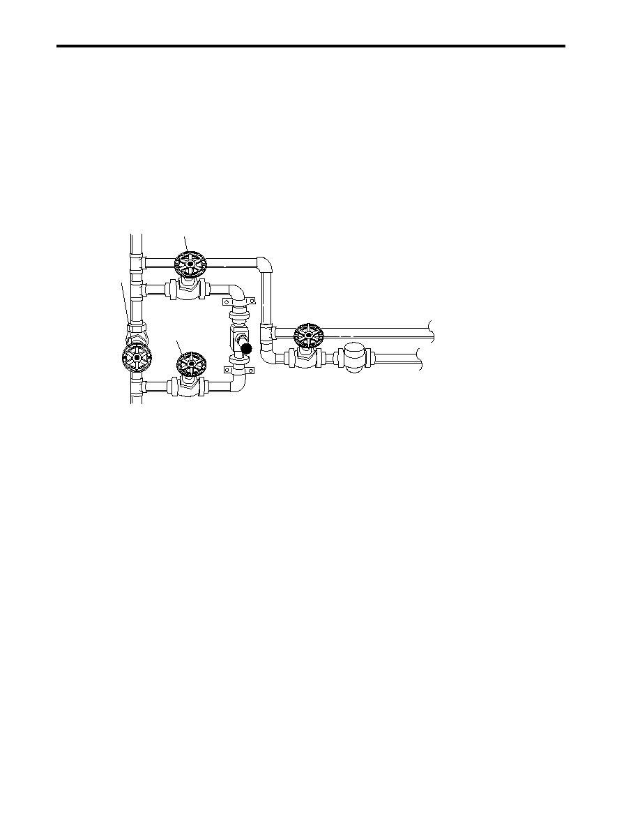
OPEN valves CA-39, SVCE AIR TK INL (figure 6, item 1), and CA-40, SVCE AIR TK INL (figure 6, item 2).
2.
Ensure that valve CA-41, BYP RDC STA (figure 6, item 3) is CLOSED.
1
3
TO PUMP
DRIVE ENGINE
2
TO BOW
THRUSTER ENGINE
Figure 6. Ship's Service Air System Valve Locations (Forward Bulkhead)
3.
OPEN valves CA-13, SVCE AIR TK INL (figure 1, item 11), CA-51, AUTO DR (figure 1, item 12), and CA-14, SVCE
AIR TK OUT (figure 1, item 13).
4.
Ensure that valve CA-48, SVCE AIR TK DR (figure 1, item 14) is CLOSED.
5.
To activate the control air system:
a.
To align the air dryer piping and valves:
(1)
OPEN the air dryer inlet valve (figure 7, item 1).
(2)
OPEN the air dryer outlet valve (figure 7, item 2).
(3)
OPEN the transducer valve (figure 7, item 3).
(4)
OPEN the filter valve (figure 7, item 4).
(5)
CLOSE the bypass valve (figure 7, item 5).
0070 00-4
|
||
 |
||