
| Tweet |

Custom Search
|
|

|
||
 TM 5-2805-261-13
1-11. REPAIR AND REPLACEMENT STANDARDS.
Table 1-1. Repair and Replacement Standards
POWERHEAD
LOWER UNIT
Piston ring gap
0.007 - 0.017 in.
Propeller shaft in front
0.001 - 0.002 in.
(0.18 - 0.43 mm)
gear bushing
(0.025 - 0.050 mm)
Piston ring groove clearance,
0.001 - 0.004 in.
Rear reverse gear to
0.0005 - 0.002 in.
lower
(0.038- 0.102 mm)
rear bushing
(0.013 - 0.050 mm)
Piston pin to piston - loose
0.001 in.
Reverse gear bushing to
0.0005 - 0.0010 in.
end
(0.025 mm)
propeller shaft
(0.013 - 0.038 mm)
Cylinder and piston
0.0005 - 0.0030 in.
Propeller on shaft at drive
0.0007 - 0.0030 in.
(0.013 - 0.076 mm)
pin hole
(0.018 - 0.076 mm)
Crankshaft end play
0.0011 - 0.0030 in.
Propeller on shaft - above the
0.0007 - 0.0034 in.
(0.028- 0.76 mm)
shoulder
(0.017 - 0.086 mm)
Section III. TECHNICAL PRINCIPLES OF OPERATION
1-12. SECTION OVERVIEW. this section contains a description of how the outboard motor works. Paragraph 1-13 describes the
operation of the components. Paragraph 1-14 describes the unit as a whole.
1-13. OUTBOARD MOTOR FUNCTION.
A. POWERHEAD. The engine component of the unit. Provides 40 horsepower to drive the propeller. The sequences (views)
below give a brief description of engine operation.
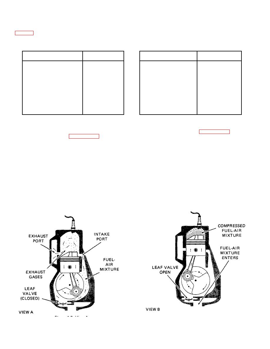
View A shows the fuel intake and gas exhaust stage which occurs immediately after firing. Note that the exhaust and intake ports
have been uncovered by the piston. Gas vapors resulting from the explosion are exiting through the exhaust port. At the same time
a fuel-air mixture in the crankcase is being compressed and forced upward through the intake port, expelling any remaining gas vapor
through the exhaust port. At this point the leaf valve is closed. The leaf valve controls the direction of flow of the fuel-air mixture from
the carburetor into the crankcase cavity.
As the piston starts its upward or compression stroke, a partial vacuum is created in the crankcase and atmospheric pressure forces
the leaf valve open, allowing the next combustible charge to enter the crankcase cavity. By this time the piston has compressed the
intake mixture against the cylinder head preparatory to firing.
Figure 1-3. View A
Figure 1-4. View B
1-5
|
||
|
||


