
| Tweet |

Custom Search
|
|

|
||
 TM 55-1905-217-12
the three bilge pumps. Open valves as needed to pump
water out of the bilge compartments.
(17) On hull numbers 8540 through 8560 and
8580 through 8618 incorporate clutch drive bilge pumps.
As shown in fig. 1-14.2 , two pumps are driven
by the port inboard engine and one pump is driven by the
starboard inboard engine. Each pump incorporates a
friction drive clutch plate and manual clutch lever. The
belt driven pulley on each pump is engaged or
disengaged with the pump shaft and impeller by
movement of the clutch lever. The clutch normally is
disengaged and would be engaged only when needed to
drain a compartment. The clutch can be engaged or
disengaged at any engine rpm.
(18) The bilge pump overboard discharge valves
and one valve is located on the starboard side. All three
valves must be open when engines are running. In hull
numbers 8500 thru 8539, all three valves must be open
when engines are running.
(19) The nine bilge line valves (fig. 2-14) are
located forward in the engine room. These valves are
opened as needed to pump out the various bilge
compartments.
(20) The hydraulic steering suction valve, hull
numbers 8500 through 8519 (fig. 2-16), is located at
bottom of steering system tank in the engine room. The
valve must be open before engines are started. The
Gunderson and Rohr crafts do not have a valve for this
purpose because the hydraulic fluid is pumped out
through the top of the tank.
(21) The ramp hoist hydraulic system supply
valve, hull numbers 8500 thru 8519 (fig. 2-16), is located
at bottom of ramp hoist system tank in the engine room.
This valve must be open when the ramp hoist system
pump is operating. Close this valve only for periods of
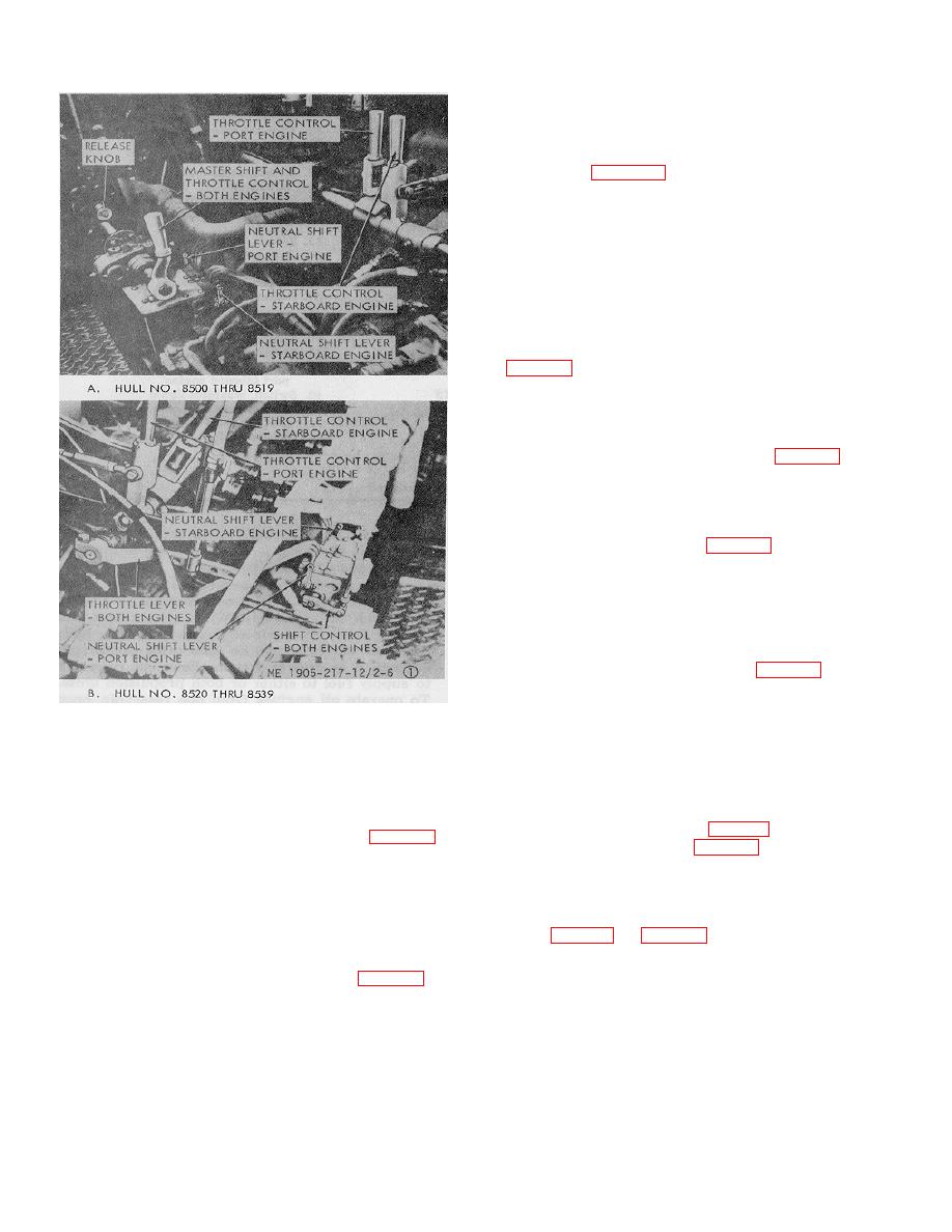
Figure 2-6.1. Engine control in engine room
maintenance or prolonged shutdown. Hull numbers 8520
(Sheet 1 of 2)
thru 8560 and 8580 thru 8618 do not have a valve for this
purpose because the suction line enters the tank through
When open they allow inlet flow of sea water
the top.
through the sea chests for engine muffler cooling. Both
(22) The hydraulic starting system tank valves,
6eacocks must be opened prior to starting the engines.
hull numbers 8500 thru 8519 (fig. 2-17) and 8540 thru
(14) Two sea water discharge valves (fig. 2-13)
8560 and 8580 thru 861-8 (fig. 2-18), are located at
are located on each side of the engine room. These
bottom of tank on starboard side of engine room. Valves
valves must be opened (1/2 open) before engines are
must be open when engines are running. Hull numbers
started.
8520 thru8539 do not have similar valves.
(15) The bilge pump prime valves are located in
(23) The starting system accumulators and
prime lines between the sea water system and the three
valves (fig. 2-19 and fig. 2-20 for hull numbers 8540
bilge pumps. The valves must be opened before engines
through 8560 and 8580 thru 8618). Two accumulators
are started.
with shutoff valves are located in
(16) The bilge pump suction valves (fig. 2-14)
are located in the suction line to each of
2-8
|
||
|
||


