
| Tweet |

Custom Search
|
|

|
||
 TM 55-1905-217-34
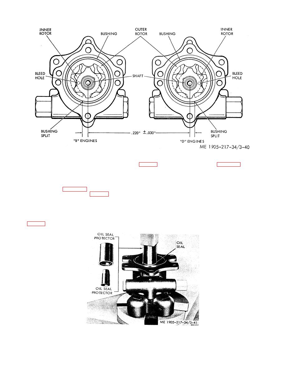
Figure 3-40. Oil pump porting and rotors including bleed holes.
NOTE
When installing the rotor bushing (20, fig. 3-39) in the oil pump body, refer to figure 3-40
for the proper location of the split in the bushing for "B" or "D" engine oil pumps. The
outboard engine of the port propulsion unit and the inboard engine of the starboard
propulsion unit are "B" engines. The inboard engine of the port propulsion unit and the
outboard engine of the starboard propulsion unit are "D" engines.
(2) Refer to figure 3-39 and reassemble the oil pump.
(3) After the bushing (11, fig. 3-39) is installed in the oil pump cover, open the bleed hole in the cover with a 1/8
inch drill, entering from the rotor side of the cover.
(4) Tighten cover to body bolts to 30-35 ft-lb torque.
(5) Install the oil pump drive shaft oil seals (28) in the oil pump body as follows:
(a) Place the oil seal gasket (2) over the end of the shaft and into the oil seal bore in the body.
(b) Place an oil seal over the tapered end of the oil seal protector J 6904-2 with the lip of the oil seal facing down,
Figure 3-41. Installing oil seals in pump body.
3-58
|
||
|
||


