
| Tweet |

Custom Search
|
|

|
||
 TM 55-1905-219-14-1
CUB HYDRAULIC PUMP UNIT.
a. The Cub Hydraulic Pump unit (Figure 1-59) is a power source for hydraulic steering systems. The pump unit
is mounted on a 10-gallon (37.9 1) tank. An hydraulic fluid level gauge is located on the side of the sump tank. A 100-
mesh strainer, located in the sump, filters the fluid. An electric motor drives the pump unit.
b. The Vane Pump is a rotary, single-stage sliding vane unit consisting of a housing and rotor assembly. The
rotor has a series of slots into which are fitted vanes. As the rotor turns, the vanes are thrown outward by centrifugal force
to bear against the surface of an oval shaped cam. As the vanes move across the inlet chamber, the radius of the oval
cam increases to create an increasing space between the rotor and the cam. Atmospheric pressure acting upon the inlet
fluid forces it into this space. Fluid is trapped between vanes as they move past the inlet chamber. At this point, the
radius of the contour decreases and the fluid is forced into the outlet chamber.
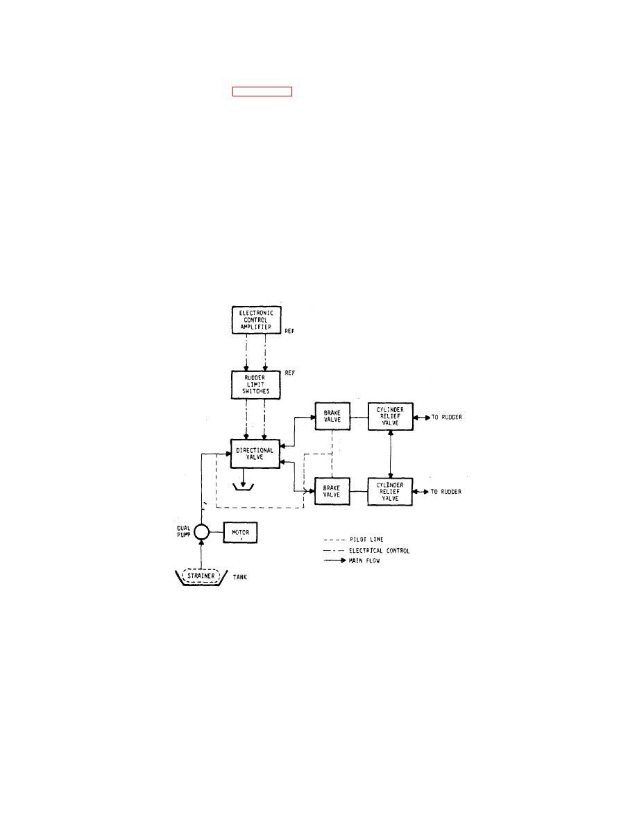
c. The Directional Valve is a solenoid operated valve which controls flow to operate the rudder. This valve is
electrically controlled from the external electronic control amplifier. The solenoids of the valve are de-energized if the
rudder limit switches are activated. Brake valves lock the cylinders in any position when no changes are being ordered.
The cylinder relief valves are connected across the lines that link the pump unit to the rudder positioning cylinders. These
valves limit pressure build-up as a result of an object striking the rudder by allowing the rudder to move even though the
brake valves are closed. This prevents damaging the steering gear.
|
||
|
||


