
| Tweet |

Custom Search
|
|

|
||
 TM 55-1905-222-14
6-14
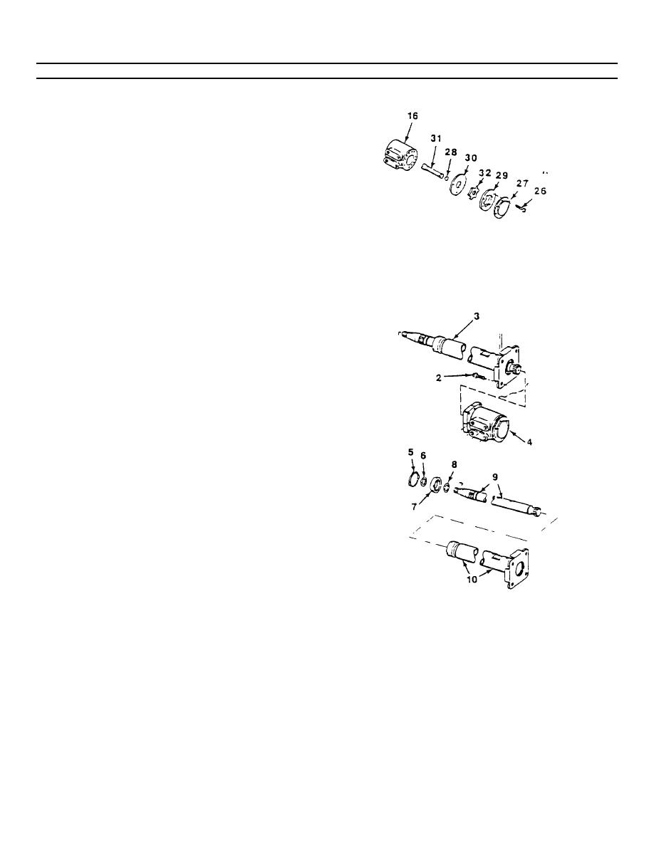
REPAIR HELM UNIT (Continued).
b.
Place the splined end of the drive shaft (31)
within the meter gear star (32) so that the slot at
the control end of the drive shaft is in
alignment with the valleys between the meter
gear teeth. Push the splined end of the drive
shaft (31) through the meter gear star (32) so
that the spline extends about one half its length
beyond the meter gear star.
c.
Install the drive shaft and meter gear star
assembly onto the housing so that the meter
gear star (32) fits into the meter gear (29).
d.
Rotate the meter gear star (32) slightly to
bring the cross slot of the drive shaft (31) into
engagement with the centering pin.
e.
Install the spacer (28) in :he slot of the meter
gear star (32) so that it is flush with the gear
surface. (If the spacer does not drop flush with
the gear surface, the drive has not properly
engaged the centering pin.
f.
Install the end cap (27) and secure with six
capscrews (26). Torque evenly to 150 pound -
inches.
3.
ASSEMBLE AND INSTALL SHAFT AND FLANGE
ASSEMBLY.
a.
Install retaining ring (8), bearing (7) and
retaining ring (6 and 5) onto shaft (9).
b.
Install shaft assembly into flange unit (10).
c.
Install shaft and flange assembly (3) into the
control and metering assembly (4).
d.
Secure unit with four mounting bolts (2).
6-79
|
||
|
||


