
| Tweet |

Custom Search
|
|

|
||
 TM 55-1905-223-24-18-1
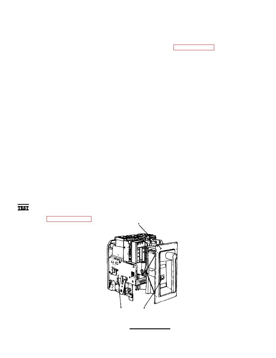
(5) Ensure racking cams on breaker are positioned for engagement with pins
in compartment.
a.
Insert racking handle (7) into racking screw hole (2, FIGURE 2-223) and turn
counterclockwise until jack screw comes to solid stop. Remove racking handle
(7).
b.
Attach suitable lifting device and spreader rig and raise circuit breaker (1)
above elevation of tracks.
c.
Slowly lower and guide circuit breaker until circuit breaker (1) mounting
pins drop into track slots on substructure (3).
Remove lifting device and spreader rig.
d.
Manually push circuit breaker (1) in until it reaches track stops (DISCONNECT
e.
position).
f.
Close door panel (9, FIGURE 3-179).
Turn door panel screws (4) clockwise until tight.
g.
h.
Insert racking handle (7) into racking screw hole (8) and turn handle (7)
clockwise until jack screw comes to solid stop (CONNECTED position). Remove
racking handle (7).
i.
Store racking handle (7) behind door panel (3).
Install door panel (3).
j.
Turn door panel screws (1) clockwise until tight.
k.
Refer to paragraph 2-298.
2-898
|
||
|
||


