
| Tweet |

Custom Search
|
|

|
||
 TM 55-1905-223-24-3
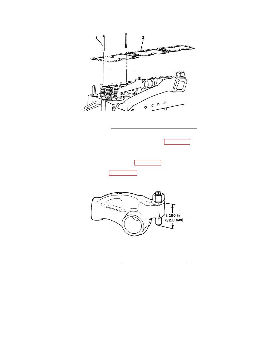
FIGURE 2-26. Rocker Housing Gaskets and Guide Studs.
d. Loosen the rocker lever setscrews so there is a maximum of 1.259 inches (32 mm) from the top
surface of the lever and the ball end of the adjusting screw (Figure 2-27).
e. Hold the rocker levers in position.
(1)
Install the ball end of the setscrews (14, Figure 2-23) in the push rod sockets.
(2)
Remove the guide studs (1, Figure 2-26).
FIGURE 2-27. Rocker Lever Adjusting Screw.
2-114
|
||
|
||


