
| Tweet |

Custom Search
|
|

|
||
 TM 55-1905-223-24-3
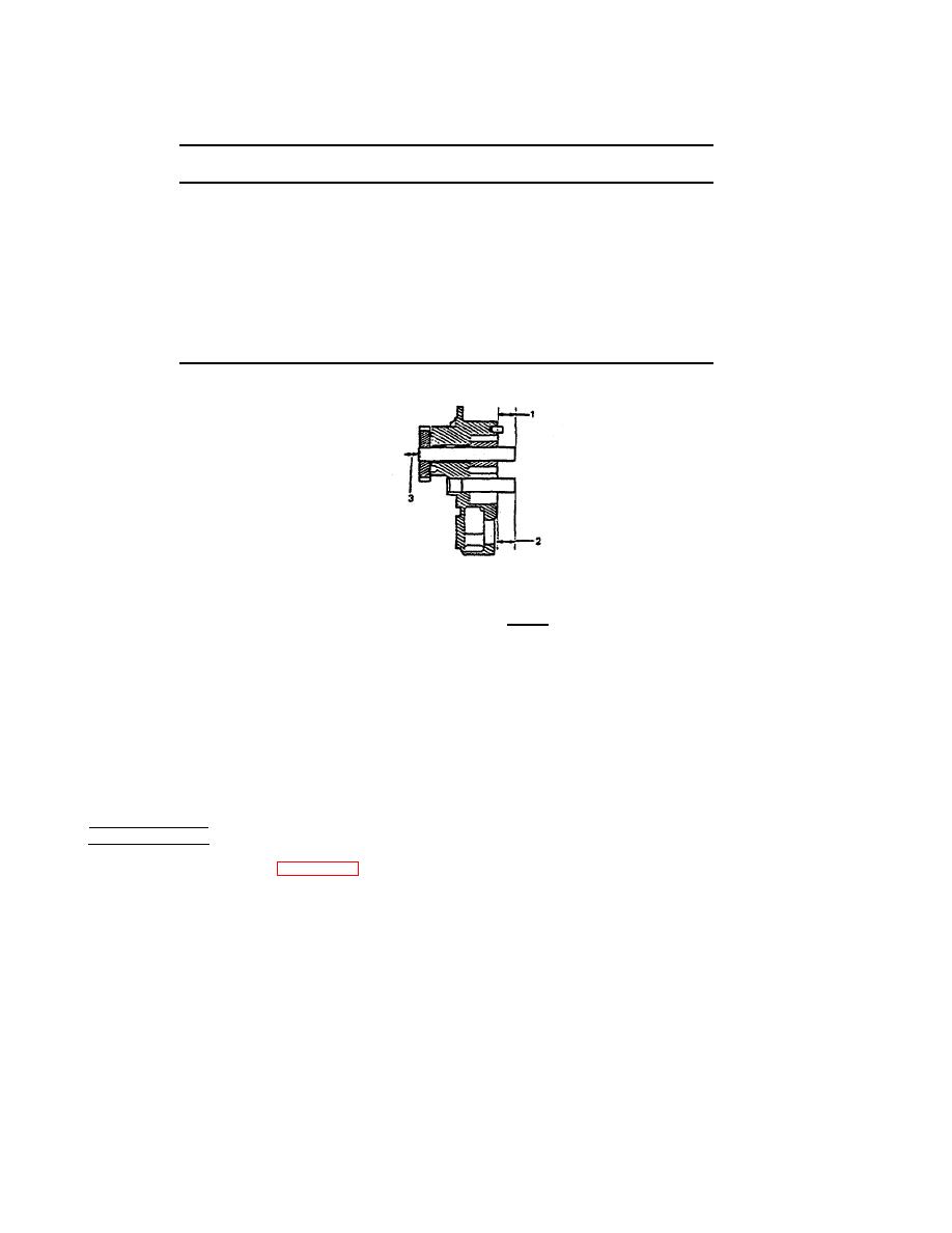
Table 3-6. Oil Pump Shaft Limits - Inch (mm)
Minimum
Maximum
Oil Pump
Drive Shaft
0.855
0.875
Protrusion 1
(21.72)
(22.22)
Idler Shaft
0.720
0.740
(18.29)
(18.80)
Protrusion 2
0.0002
0.0005
(0.05)
(0.13)
FIGURE 3-51. Limits.
g.
Apply clean lubricating oil to the gears, bushings, and shafts.
h. Install plunger (6), spring (5), plug (4), cap (3), washer (2), and capscrew (1) into the pump body (31).
Tighten the capscrew (1) to 30 to 35 ft-lb (41 to 47 N.m) torque.
i.
Install the cover (16) with capscrew (17) and gasket (15) to the pump cover (14). Install cover (14) with
capscrews (21). Hit the cover lightly with a rubber hammer to push the cover onto the dowels. Install
the
capscrews (17) and lockwashers so that the cover is held to the body. Tighten the capscrews to 30-
35 ft-lb
m
REPLACEMENT
a.
Install new gasket (32, Figure 3-51) onto the mounting flange of the oil pump,
b. Position the pump onto the mounting hole in the, cylinder block. Make sure that the gear teeth of the
pump align with the camshaft gear teeth.
3-98
|
||
|
||


