
| Tweet |

Custom Search
|
|

|
||
 TM 55-1905-223-24-3
j.
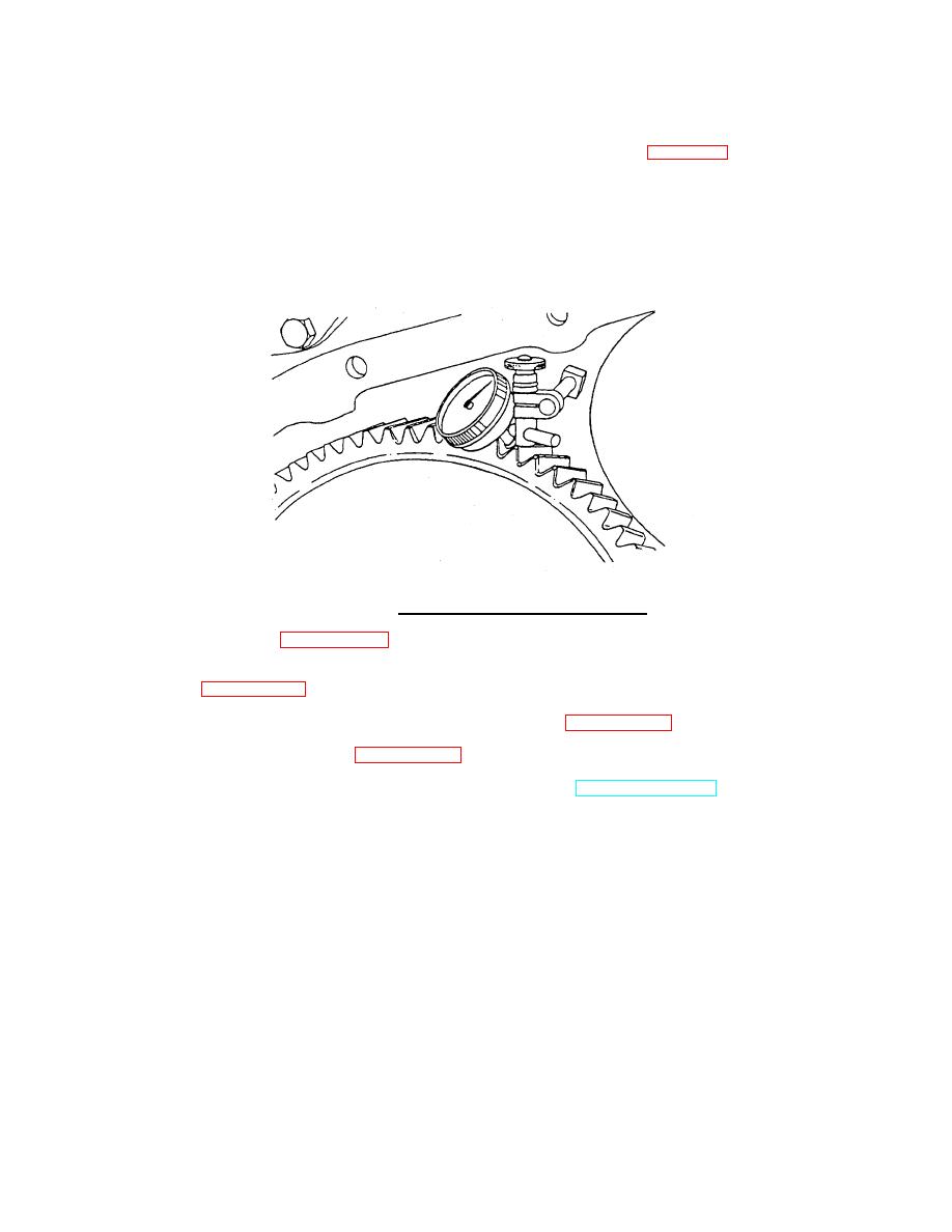
Use a dial indicator to check the backlash between the camshaft gear and the crankshaft gear.
(1)
Put the tip of the dial indicator against a tooth on the camshaft gear (Figure 3-55).
(2)
Turn the camshaft gear by hand as far as it will freely move, and set the dial indicator at "0"
(zero).
(3)
Turn the camshaft gear by hand in the opposite direction as far as it will freely move, and
read the dial indicator. Backlash between the camshaft and the crankshaft gears should be
between 0.002 inch (0.05 mm) and 0.20 inch (0.50 mm).
FIGURE 3-55. Camshaft Gear Backlash Measurement.
k.
Install the gear cover (paragraph 3-20).
l.
Lubricate the valve and the injector lobes with engine lubricating oil, and install the cam follower
housing (paragraph 3-18).
m.
Install the crankshaft pulley and the vibration dampener assembly (paragraph 3-26).
n.
Install the accessory drive pulley (paragraph 3-19).
o.
Connect battery banks (starboard), operate air system (port), refer to TM 55-1905-223-10.
p. Operate the engine until it reaches a temperature of 180 (80 ), and check for coolant or lubricating
F
C
oil leaks.
3-103
|
||
|
||


