
| Tweet |

Custom Search
|
|

|
||
 TM 55-1905-223-24-3
(e)
Record the indicator reading at three different points: 3 o'clock, 6 o'clock, and 9
o'clock.
(f)
Continue rotating the crankshaft until the dial indicator is at the 12 o'clock position.
(g)
Check the dial indicator to ensure the needle still points to "0" (zero).
NOTE
If the dial indicator is not pointing to "0" (zero), check the tightness of the
indicator arm and repeat steps (a) through (g) above.
(h)
Determine the Total Indicator Reading (TIR) as follows:
mm
in
Example:
12 o'clock
( 0.00)
0.00
3 o'clock
(+ 0.08)
+ 0.003
6 o'clock
(- 0.05)
- 0.002
9 o'clock
(+ 0.08)
+ 0.003
Equals TIR
( 0.13)
0.005
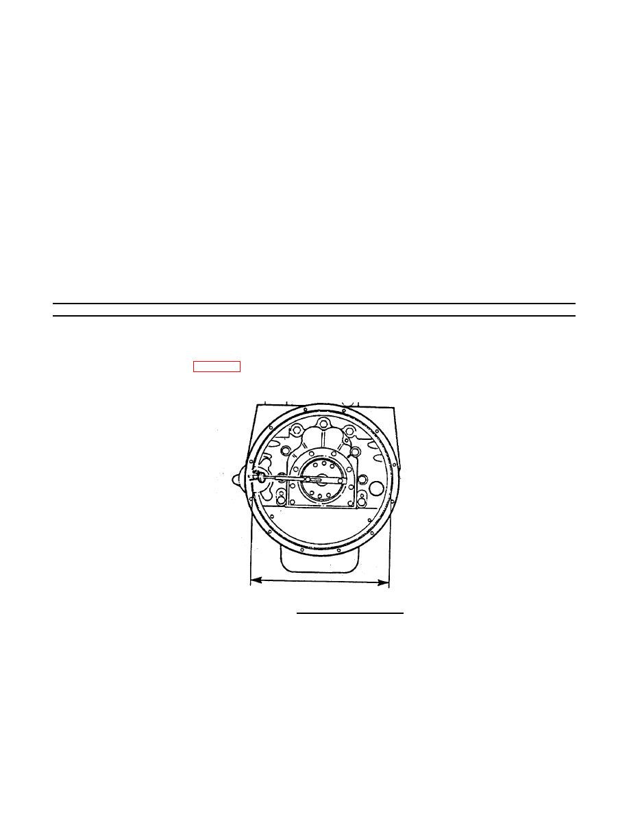
(i)
The maximum allowable TIR depends on the diameter of the housing bore (Figure 3-
72).
(j)
Refer to Table 3-7 for allowable TIR.
FIGURE 3-72. Housing Bore Diameter
3-120
|
||
|
||


