
| Tweet |

Custom Search
|
|

|
||
 TM 55-1905-223-24-3
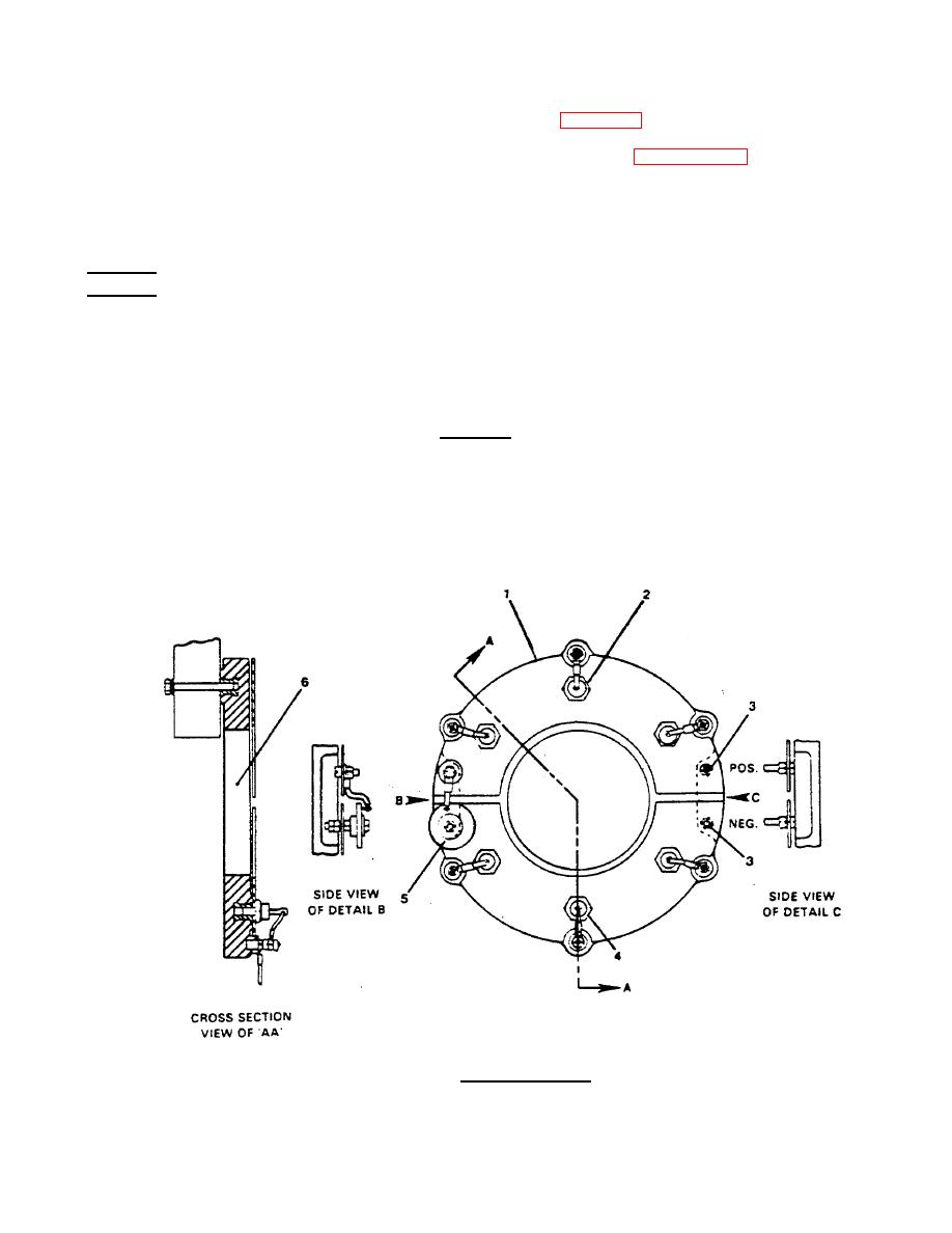
(1) Tag and disconnect the wiring to the rectifier assembly (Figure 4-4).
(2) Remove the diodes (2, 4) from the rectifier assembly (1). Refer to paragraph 3-13.
(3) Disconnect the lead and remove the varistor lead assembly (5).
(4) Remove the nut and washers at points (3) from the positive and negative plates. Remove the
plates from the molded base (6).
REPAIR
Repair to the internal generator assembly consists of cleaning, inspecting, and replacing the defective parts or
assemblies that were removed in the disassembly step of this procedure. Replacement of a faulty varistor is
also included in this section.
a. Clean internal parts and windings.
CAUTION
Do not use wire brushes for cleaning.
(1) Dust and dirt may be removed by brushing with bristle brushes, followed by vacuum cleaning.
Vacuum cleaning is an effective and desirable method of removing dry and loose dirt since it does
not scatter the dirt.
EXCITER ROTOR CORE
FIGURE 4-4. Rectifier Assembly
4-10
|
||
|
||


