
| Tweet |

Custom Search
|
|

|
||
 TM 55-1905-223-24-3
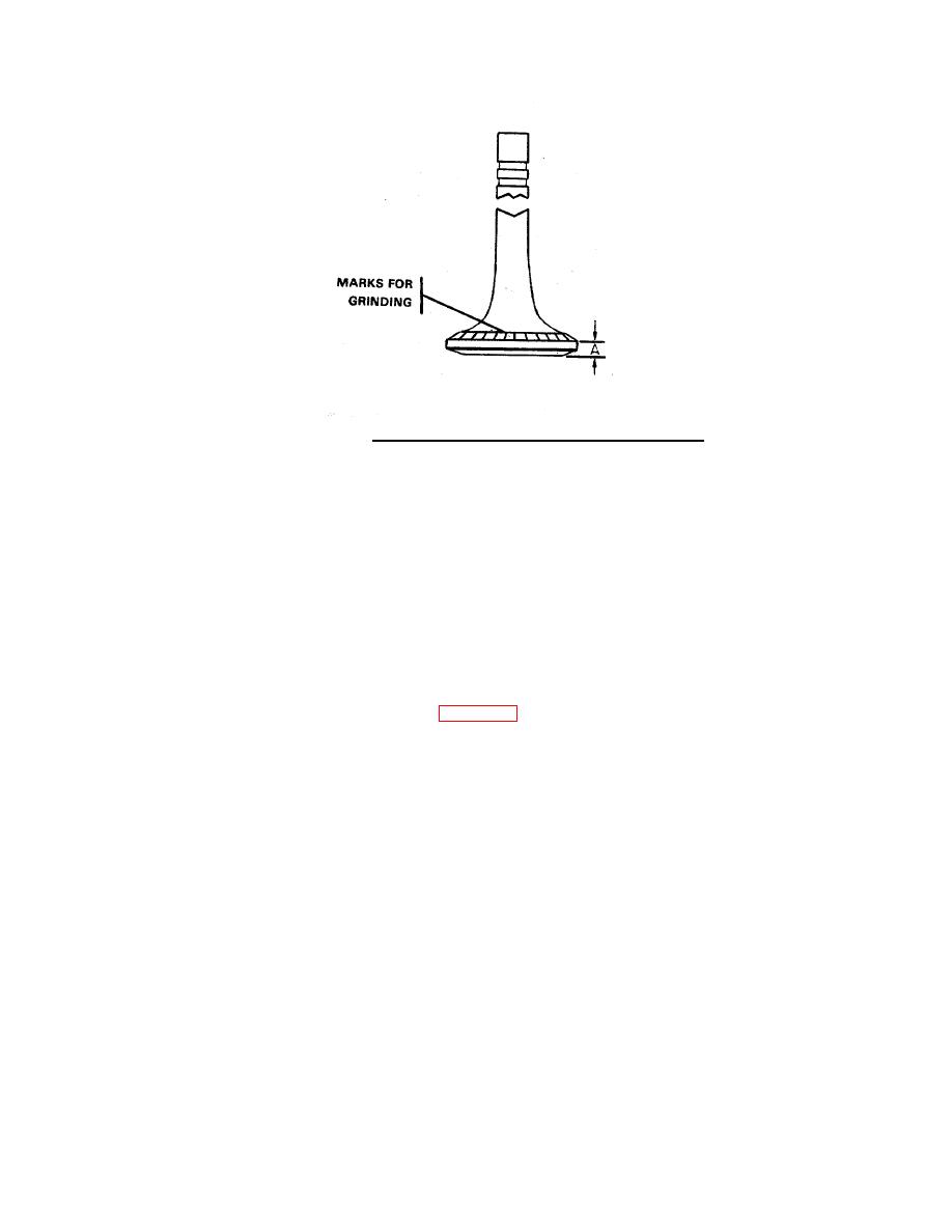
FIGURE 4-11. Rim Measurements and Grinding Marks.
(h) Repeat steps (b) and (c).
(i)
If the highest indicator reading is the same, and in the same location of the face when the valve is positioned
as in steps (a) and (d) the valve is distorted.
(j)
If the highest readings are at different locations on the valve face in steps (a) and (d), the chuck is not in
alignment.
(k) The indicator must not show more than 0.001 inch (0.02 mm) difference around the circumference of the
valve face.
(l)
Grind the face of the valve. Ensure the coolant will spray on the valve head, not on the grinding wheel.
(m) Grind the valve face to an angle exactly 30 degrees from the horizontal position of the valve.
(n) Check the thickness of the valve head rim, Figure 4-11, to ensure that the rim thickness is not less than 0.124
inch (3.15 mm).
4-38
|
||
|
||


