
| Tweet |

Custom Search
|
|

|
||
 TM 55-1905-223-24-3
(6)
Measure the rod bearing shell (11) thickness with an outside micrometer that has a ball tip.
(7)
The bearing thickness should be between 0.093 inches (2.362 mm) and 0.0947 inches (2.405
mm). Replace bearing shell (11) if it is not within these measurements.
b.
Clean and inspect the connecting rods (1).
(1)
Use steam or solvent to clean the connecting rods (1).
(2)
Use a nylon bristle brush to clean the oil drillings.
(3)
Dry with compressed air.
(4)
Replace the rod (1) if the I-Beam is nicked or damaged.
(5)
Inspect the rod pin bore bushing (2) for damage or misalignment of the oil passage and the
bushing.
(6)
Use the magnetic particle detection kit to find cracks in the connecting rods (1) and machine
bolts (10). Discard the part if cracks are found.
NOTE
Some joints in the forging will show as cracks. Make sure to check the rod for
the location of these joints. These lines are not an indication of cracks. Do not
discard parts with these marks.
(7)
Inspect the connecting rod pin bushing boreand crankshaft bore.
(a) Be sure to keep the connecting rod (1) and the cap together.
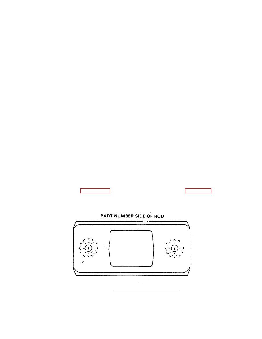
(b) Assemble the rod (1) and tighten the machine bolts (10) to the correct torque in the correct
sequence. Figure 4-31 shows the correct sequence, and Table 4-10 gives torque
specifications.
FIGURE 4-31. Connecting Rod Torque Sequence.
4-74
|
||
|
||


