
| Tweet |

Custom Search
|
|

|
||
 TM 55-1905-223-24-5
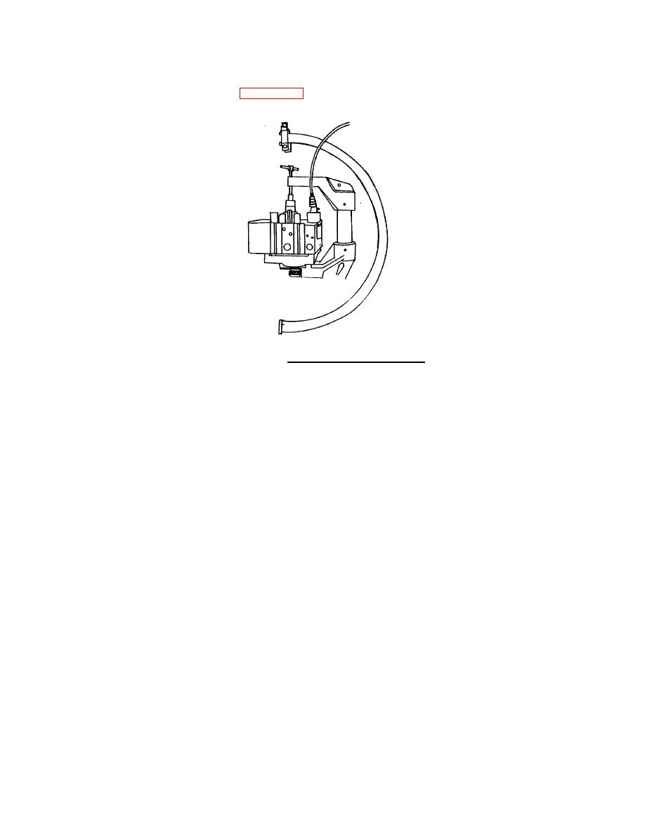
(3)
Install the cylinder head in a hydrostatic tester and hydrostatic tester
adapter plate (FIGURE 4-5) as follows:
FIGURE 4-5. Hydrostatic Tester and Plate.
(a)
Install the plates on the cylinder head. Engage the locating pins for
the plates with the holes in the cylinder head.
(b)
Install the clamping assembly over the plates on the cylinder head.
Engage the locating pins for the clamping assembly with the holes in
the plate.
(c)
Tighten the screw for the clamping assembly. Make sure the drain valve
in the adapter plate is in the closed position.
(d)
Use the pins that are supplied with the quadrant to fasten the clamping
assembly to the quadrant. Fasten the longer bracket of the quadrant to
the bottom of the clamping assembly.
(4)
Connect a regulated air supply hose to the test fixture plate.
(5)
Adjust the air pressure to 30 to 40 psi (207 to 276 kPa).
(6)
Use a hoist to place the cylinder head in a tank of warm water heated to
140 (60 ).
F
C
(7)
Completely submerge the cylinder head in the water.
(8)
Visually inspect for air bubbles rising from the water.
(9)
If air bubbles are observed, replace the cylinder head.
(10) Lift the cylinder head from the tank.
(11) Disconnect air supply hose from test fixture plate.
4-11
|
||
|
||


