
| Tweet |

Custom Search
|
|

|
||
 TM 55-1905-223-24-5
(9)
Turn the feed engaging knob (2) clockwise to engage the feed mechanism.
Attach the chuck of a 1/2-inch electric drill to the drive shank (6).
(10) Start the drill and cut the counterbore until the feed depth knob (3) is
against the gear case (8).
(a)
Let the cutter turn two or three more revolutions to make sure the
counterbore surface is even.
(b)
If the feed engaging knob (2) disengages before the knob is against the
gear case, turn the knob with your hand to complete the cut.
(11) Loosen the clamp screw (1) for the gear case. Remove the gear case (8),
arbor and cutter (11). Be careful and do not move the base or swivel.
(12) Remove all metal particles and dirt from the counterbore.
(13) Position the valve seat insert in the counterbore.
(14) Make sure the chamber on the insert is against the cylinder head.
(15) Install the driver adapter and valve seat driver through the swivel.
(a)
Hit the valve seat driver with a heavy hammer to install the valve seat
insert into the counterbore.
(b)
Make sure the valve seat goes to the bottom of the counterbore.
(c)
Remove the adapter, driver, base, and swivel from the cylinder head.
CAUTION
Be careful not to damage the cylinder head when you stake the valve seat insert.
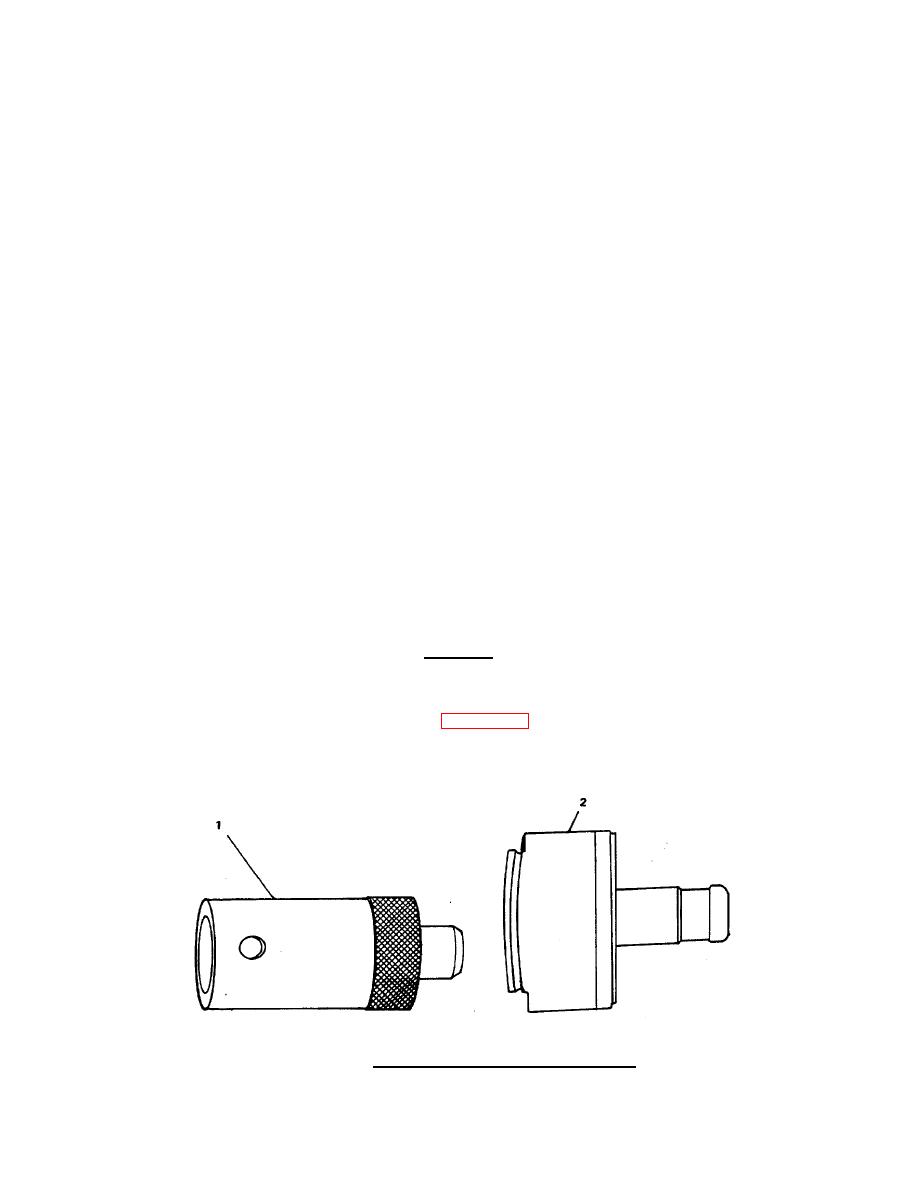
(16) Use the staking tool driver (1, FIGURE 4-8) and the staking tool (2) to
stake the valve seat insert in the cylinder head. If the staking tool
(2) and driver (1) are not available, you can use a punch to stake the
valve seat insert. Make sure the end of the punch is round.
FIGURE 4-8. Using Staking Tool Driver and Staking.
4-15
|
||
|
||


