
| Tweet |

Custom Search
|
|

|
||
 TM 55-1905-223-24-5
CAUTION
Select lifting eyebolts to obtain maximum thread
engagement with bolt shoulder tight against housing.
Bolts should be near but should not contact bottom of bolt
hole.
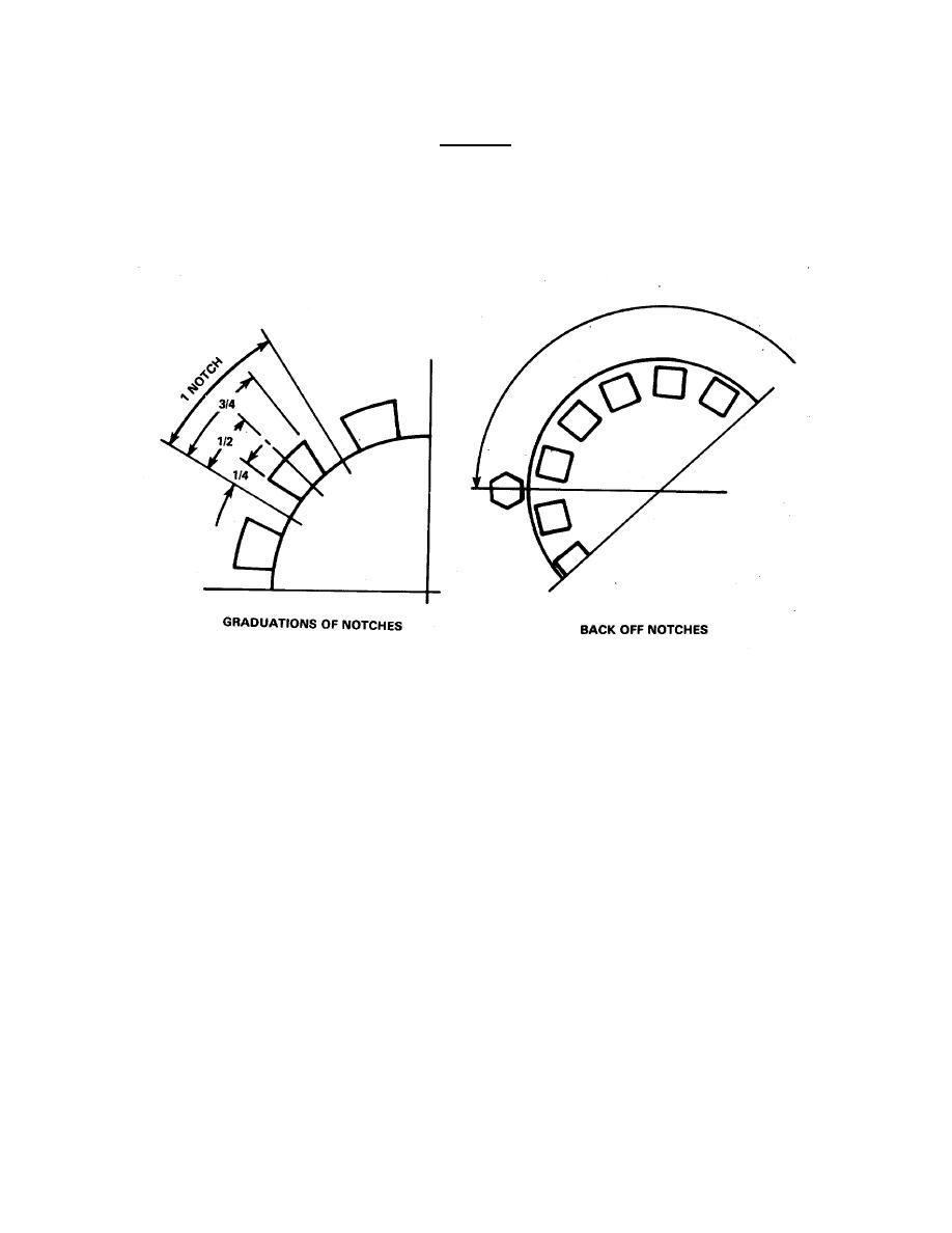
FIGURE 4-23. Adjusting Retainer Nut.
(c) Attach a dial indicator to the housing and locate the stem or plunger, from the indicator, on
the outer machined area of the end of the clutch shaft. Mark a spot next to the indicator
stem.
(d) Apply a pushing force of 200 pounds while turning the shaft two complete revolutions in each
direction (the weight of the shaft can be counted as part of the 200 pounds). With the
pushing force applied, stop the plunger or stem next to the mark and zero the dial indicator.
(e) Apply a pulling force of 200 pounds (compensate for shaft weight) to the shaft and rotate,
with force applied two complete revolutions in each direction. Stop with force applied and
mark next to plunger or stem of the dial indicator. The indicator reads the actual end play.
(f) Adjust nut to obtain the desired end play. Recheck final end play with the dial indicator as
described. Lock nut when play adjustment is between 0.004 and 0.007 inch on the SL111
HP2 (00.06 to 0.010 on the SP 214 P2).
4-47
|
||
|
||


