
| Tweet |

Custom Search
|
|

|
||
 TM 55-1905-242-14
GENERAL SUPPORT MAINTENANCE
FOR LANDING CRAFT, MECHANIZED (LCM-8) (ALL VESSELS WITH MOD 2 APPLICATION)
PROPELLER SHAFT, ALIGN
INITIAL SETUP:
Tools and Special Tools:
Personnel Required:
Tool Kit, Mechanic's Rail and Marine (Item 1,
Two Watercraft Engineers, 88L
Table 1, WP 0230 00)
References:
Dial Indicator (Item 5, Table 1, WP 0230 00)
FM 55-502
Equipment Condition:
Propulsion engines secured, locked out, and
tagged out IAW FM 55-502
Vessel afloat for final alignment
ALIGNMENT
NOTE
Propeller shaft alignment is not permanently fixed. The alignment changes with every
docking due to changes in the keel blocking, temperature variations, and the direction of
the sun's rays relative to the fore and aft line of the vessel. The alignment of shafting is
affected by the temporary removal of machinery attached to the shafting or in the
vicinity of the shafting because of the redistribution of weights and stresses. The
alignment is not the same when the vessel is waterborne as when it is in drydock. The
final alignment and bolting of the main propulsion shafting should always be done
when the vessel is waterborne.
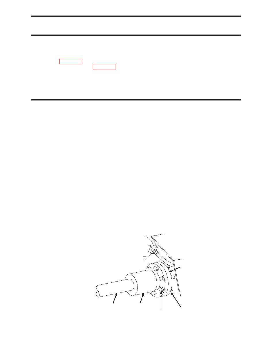
1.
Remove the bolts (1) and nuts (2) that secure the shaft coupling (3) to the transmission output flange (4).
2.
Slide the propeller shaft (5) back to allow clearance between the shaft coupling (3) and the transmission output
flange (4).
3.
Clean the mating faces of the shaft coupling (3) and the transmission output flange (4) with a wire brush, ensuring that
both surfaces are clean, smooth, and free of corrosion.
4.
Fasten the dial indicator fixing stand (6) to the shaft coupling (3) as shown to check the angular alignment.
4
3
5
2
1
0202 00-1
|
||
|
||


