
| Tweet |

Custom Search
|
|

|
||
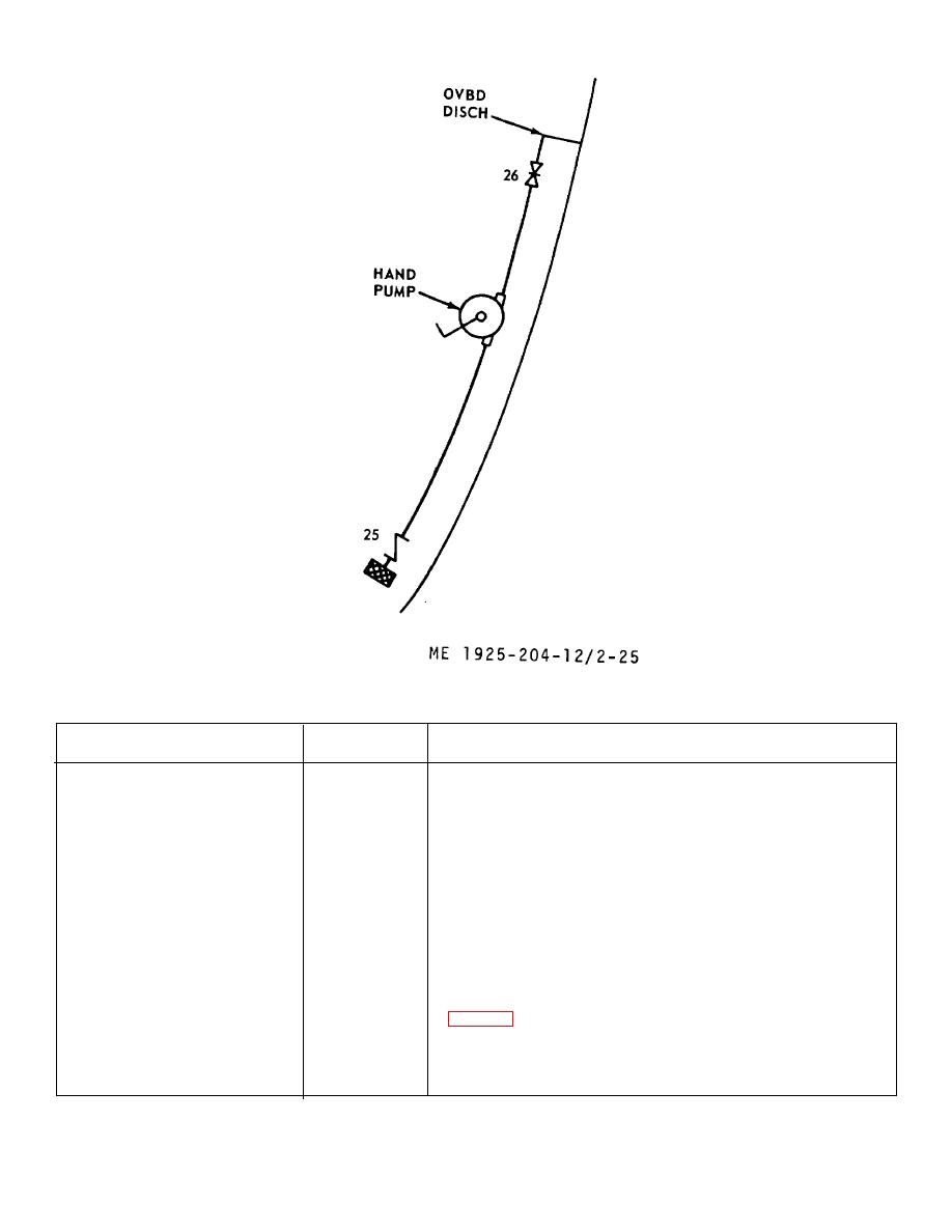 Figure 2-25. Chain locker bilge piping diagram.
Table 2-14. Bilge and Ballast System Control Value Positioning.
Operation
Open valve
Procedure
Pump engine room and void space
(3)
Open valve (7) and start bilge pump. Pump until bilge is dry.
bilges.
(5)
Close valve (7). Repeat procedure for valve (8) and (9)
(6)
Secure pump. Secure all valves.
(20)
Pump crew's quarters and storage
(5)
Open valve (21) and start bilge pump. Pump until bilge is dry.
compartment bilges.
(6)
Close valve (21). Repeat procedure for valves (22), (23) and
(20)
(24). Secure pump. Secure all valves.
Pump chain locker bilge.
(26)
Prime pump if necessary. Crank handle on chain locker bilge
hand pump until bilge is dry. Secure valve (26).
Use independent bilge suction
(2)
Connect hose to independent bilge suction connection and
connection.
(5)
drop other end into area to be pumped. Start bilge pump
(6)
and pump until dry. Remove hose. secure pump..
(20)
Secure all valves.
Fill fore peak ballast tank.
(1)
Start bilge pump. Take soundings of fore peak tank
(5)
(6)
Secure all valves.
(13)
(17)
(18)
2-50
|
||
|
||


