
| Tweet |

Custom Search
|
|

|
||
 TM 55-1925-204-12
(d) Connect the inlet and outlet fuel lines
(b) Remove the three capscrews with
to the fuel pump.
assembled washers, then lift the fuel pump and pump
i. Blower.
The blower is designed for diesel
drive coupling fork from the blower.
(2) Installation.
operation, and supplies fresh air from the air cleaner for
combustion and scavenging.
(a) Position a new gasket on pump body
(1) Removal. Drain the engine cooling system,
mounting flange, and locate the pump drive coupling
fork over the squared end of the drive shaft, with prongs
then remove governor (g. (1) above) and governor drive.
of fork directed away from the pump.
(a) Remove fresh water pump (f, (1)
(b) Position the fuel pump up against the
above).
blower, with the prongs of the drive coupling fork lined up
(b) Remove the fuel pump (h., (1)
with the slots in drive disc on the blower rotor shaft.
above).
(c) Secure pump to blower with three
(c) Disconnect the control wire from the
capscrews and assembled washers.
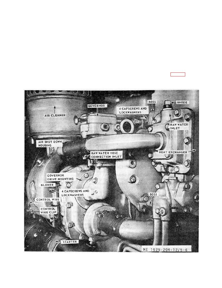
air shut-down valve shaft lever (fig. 5-6), then remove
capscrew anchoring the control wire clip to the air
housing.
Figure 5-6. Blower, and air inlet housing.
5-8
|
||
|
||


