
| Tweet |

Custom Search
|
|

|
||
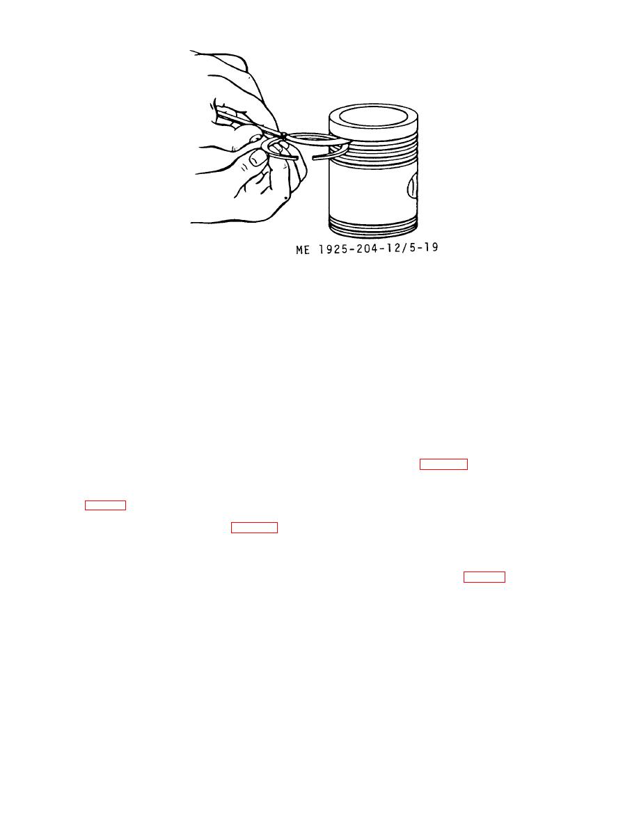 Figure 5-19. Checking piston ring side clearance.
(10) Fit piston pin into connecting rod sleeve
(3) Position upper end of connecting rod in line
bearing. If pin to bearing clearance exceeds 0.010 inch,
with pin aperture. Lubricate piston pin (15) with clean
determine which is worn. If pin diameter is less than 1.4990
lubricating oil, and slide it into position.
inch, replace the pin. If inside diameter of bearing is more
(4) Insert the second cap (13) behind piston pin
than 1. 5020 inch, replace the bearing.
and tap it into position.
(11) Inspect and open hole in orifice at lower end,
(5) Install oil ring expanders in grooves on skirt of
and holes in spray nozzle at upper end of the connecting rod.
piston, then install oil control rings (10) in grooves over the
Blow dry compressed air through the passages to be sure
expanders.
they are all open.
(6) Install compression rings (14) in grooves at
(12) Because the connecting rod bearing load is on
top of piston, putting ring in fourth (bottom) groove first, then
the upper half, any wear will show only on the upper half.
up to next groove until all are in place. Move rings in grooves
Examine upper bearing halves for scoring, chipping,
until end gaps are 900 from each other.
corrosion, cracking, or the discoloration caused by
overheating. Inspect the backs of bearing halves for any.
NOTE
bright spots that indicate halves have been moving in their
Be sure that cylinder liner has been
support, and are unfit for further use. Replace bearings where
serviced (para 5-5) before pistons are
any of the above defects exist.
installed.
(13) Inspect journals of the crankshaft. If they are
scored, or show the discoloration of overheating, replace the
f. Installation.
crankshaft (para 5-8).
(1) Lubricate surface of piston and rings with
e. Reassembly.
clean engine oil, stagger end gaps at 90around piston, then
(1) If sleeve bearings (8 or 12, fig. 5-16) were
use ring compressor and compress rings into their grooves.
removed, install them now.
(2) Lower piston rod into liner with the identifying
(2) Insert a serviceable cap (13) in one end of the
number on rod toward the blower side of the block. Align the
piston pin aperture and drive it into position.
connecting rod bearing with the connecting rod journal, and
push the piston into the liner (fig. 5-20).
5-23
|
||
|
||


