
| Tweet |

Custom Search
|
|

|
||
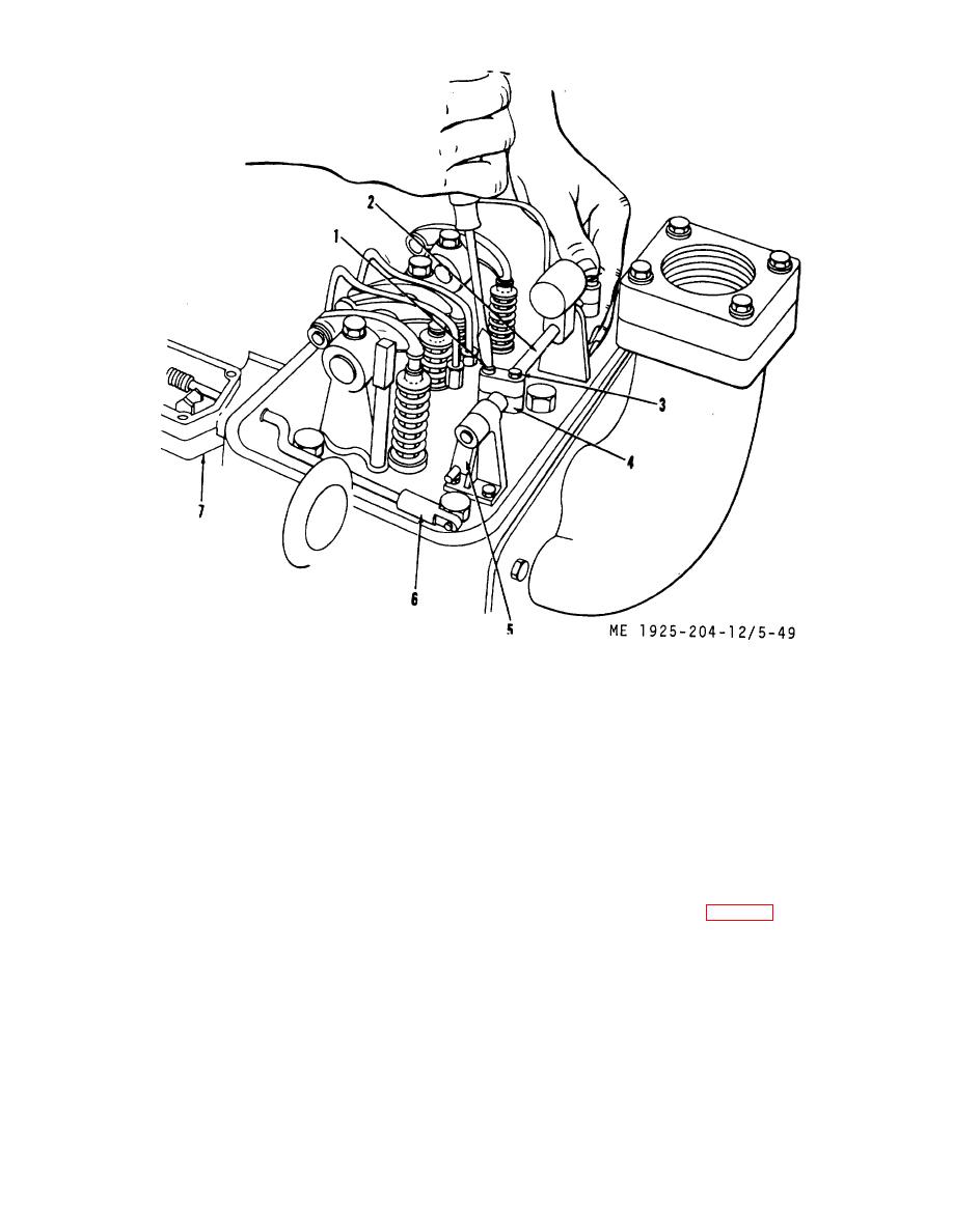 1.
Adjusting screw. rack
5.
Lever. injector control tube
2.
Tube, injector control
6.
Rod. governor, subcap. fuel
3.
Adjusting screw. rack control lever (outer)
7.
Governor and drive assembly
4.
Lever. injector rack
Figure 5-49. Positioning injector control rack.
(5) Adjust rack control lever adjusting screws (1)
(8) Check injector fuel rod (6) and control tube (2)
and (3) on No. 1 injector rack lever (4) (water pump end of
for binding. Parts must move freely.
engine), so that upper half of lever is straight (not cocked)
(9) Hold injector racks in NO FUEL position and
with respect to lower half. Tighten adjusting screws (1) and
adjust clevis on injector shaft end of fuel rod (6) until hold in
(3).
clevis just slides over pin in lever (5). Replace washer and
(6) Loosen rack control lever screws (1) and (3)
retaining spring over pin on lever to hold fuel rod in place.
on No. 2 injector rack lever (4) to allow 1/8 inch play at lower
g. Maximum Fuel Adjustment.
end of lever. Push and hold No. 1 injector rack to FULL
(1) Hold fuel rod (6) in FULL FUEL (full open)
FUEL, or in position.
position and terminal lever (3, fig. 5-48) firmly against fuel
(7) Adjust No. 2 injector rack to FULL FUEL
rod collar (1).
position by turning screws (1) and (3). Turning inner screw
(2) Turn maximum fuel (load limit) screw (6)
(1) clockwise moves the injector rack toward FULL FUEL
position.
NOTE
Once FULL FUEL position is reached, do
not rotate the inner adjusting screw
further, as this will cause rotation of the
injector control tube and will move
number one injector rack from the FULL
FUEL position.
5-62
|
||
|
||


