
| Tweet |

Custom Search
|
|

|
||
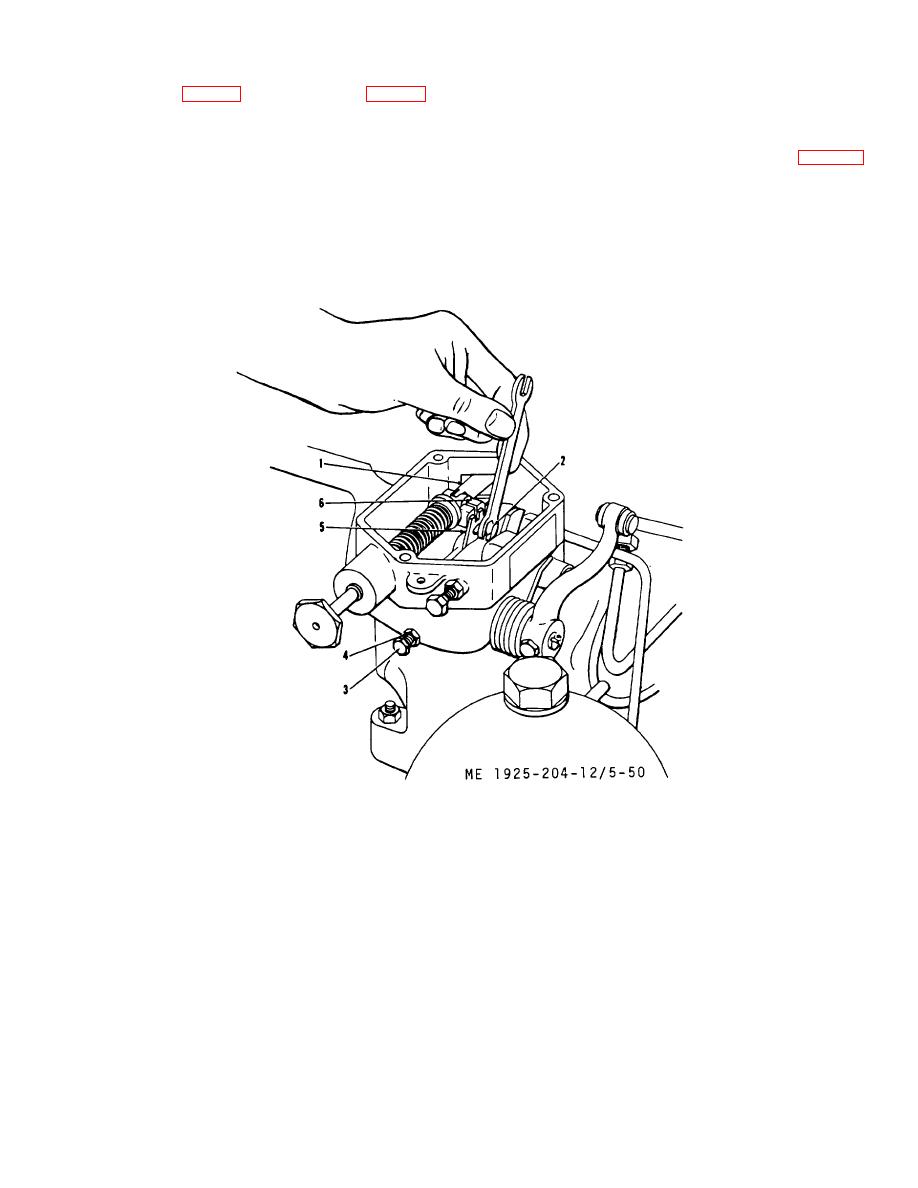 characteristic which allows engine speed to increase with a
until a 0. 020-inch gap exists between terminal lever and
decrease in load. Adjustment of speed droop is necessary
collar on fuel rod (6, fig. 5-49). Tighten locknut (5, fig. 5-48).
when governor has-been changed, or if original governor
adjustments are disturbed. Proceed as follows:
NOTE
(1) With engine stopped and governor cover
Clearance must not exceed 0. 020 inch.
removed, loosen droop bracket adjusting bolt (2, fig. 5-50)
Moving the screw too far will prevent full
and move bracket (5) so that bolt is midway between ends of
open maximum fuel) position of the
slot in bracket. Tighten bolt.
injector racks.
(3) Replace valve rocker case.
h. Speed Droop Adjustment.
Speed droop is the
governor
1.
Rod. governor subcap fuel
4.
Locknut
2.
Bolt
5.
Bracket, governor. speed adjusting lever
3.
Screw. governor high speed stop
6.
Terminal lever
Figure 5-50. Adjusting speed droop.
(2) Loosen locknut (4) on maximum speed
NOTE
adjusting screw (3) and back out screw 5/8 inch.
The speed droop bracket rides on a
(3) Start and warm engine to operating
shoulder milled in the side of the
temperature. Adjust vernier control of throttle so that engine
terminal lever. Hold bracket firmly in
no-load speed, checked with an accurate tachometer, is
place on shoulder when tightening
1,250 rpm and generator output is 125 volts.
adjusting bolt.
If bracket is not
(4) Move main switch (circuit breaker) to ON
positioned in this manner, the bracket
position; this will place full-rated generator load on
will be bent when tightening the
adjusting bolt and the governor action
will be erratic.
5-63
|
||
|
||


