
| Tweet |

Custom Search
|
|

|
||
 (c) Untact weld of three braces from bottom
a dirty commutator with 00 sandpaper. Replace brushes worn
mounting flange, then lower housing to grating in fidley (fig.
until less then 1/2 inch protrudes from holder. Sand new
brushes to contour of the commutator. Adjust brush tension
(TM 55-506).
(3) Disassembly.
(a) Remove screen assembly from bell housing.
(2) Removal.
(b) Remove hood screws, and remove hood (1,
(a) Tag and disconnect external wiring from the
motor.
(b) Remove nuts and bolts from upper mounting
flange of blower housing.
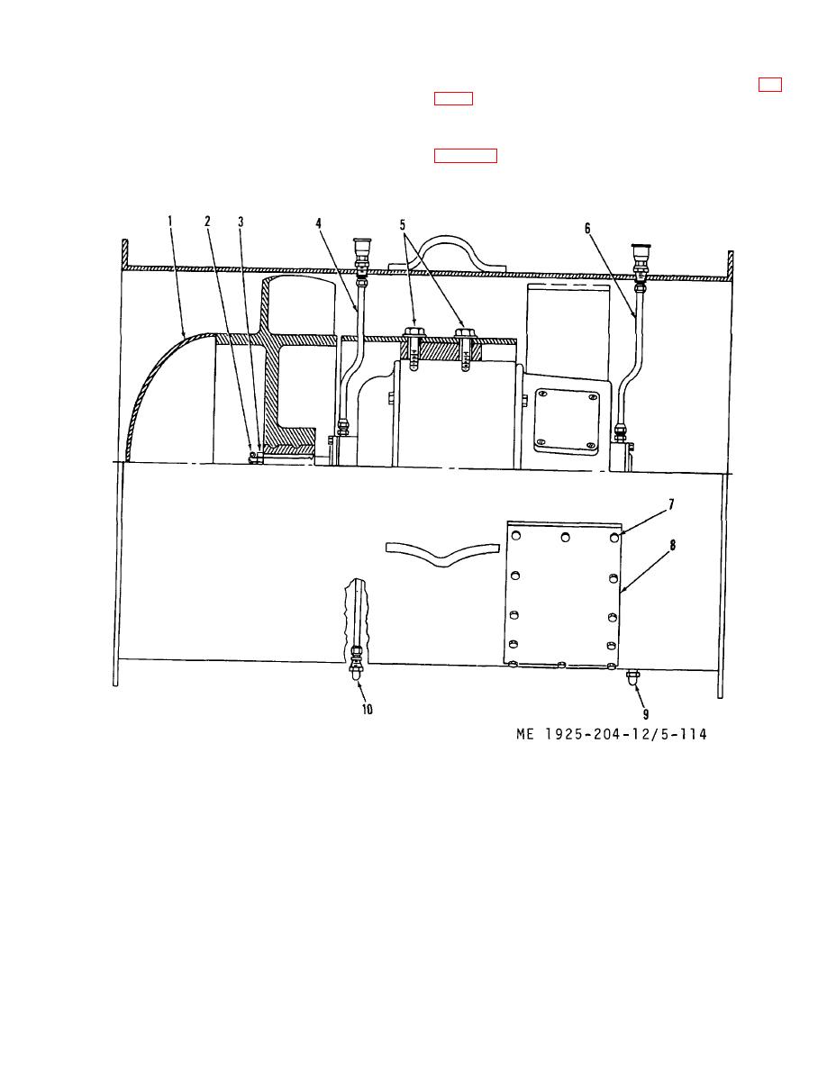
1.
Hood
7.
capscrews
2.
Cotter pin
8.
Access door
3.
Nut
9.
Lower grease drain
4.
Upper grease supply tube
10.
Upper grease drain
5.
Capscrews
6.
Lower grease supply tube
Figure 5-114. Axial blower assembly, sectional view.
(c) Remove cotter pin (2) and castellated nut (3)
(f)
Loosen nuts on grease tubes and drains (4, 6,
from fan shaft.
9, and 10).
(d) Pull fan from motor shaft.
(g)
Unscrew grease tubes and withdraw from fan
(e) Remove key which holds fan in position on
housing.
shaft.
5-160
|
||
|
||


