
| Tweet |

Custom Search
|
|

|
||
 TM 55-1925-273-10-1
0039 00
brake, because the carrier cannot rotate against a stationary main shaft unless the orbit gear is also permitted to rotate. Thus,
braking of the orbit gear results in braking of the drum.
During certain operating modes, for example use of the gypsey heads, the drum (figure 12, item 3) must remain stationary
while the main shaft rotates. The auxiliary brake (figure 12, item 5) secures the brake drum during these operations. This
braking action is accomplished by pulling a friction-lined brake band tight against the outer diameter of the drum.
A level wind assembly (figure 12, item 6) is provided on each towing machine. The level wind assembly is driven by a
worm gear shaft (figure 12, item 7) that rotates in response to drum (figure 12, item 3) rotation. This assembly helps to
ensure that the wire rope always winds evenly onto the drum. Alignment and adjustment of the level wind assembly is
accomplished with the adjusting wheel (figure 12, item 8).
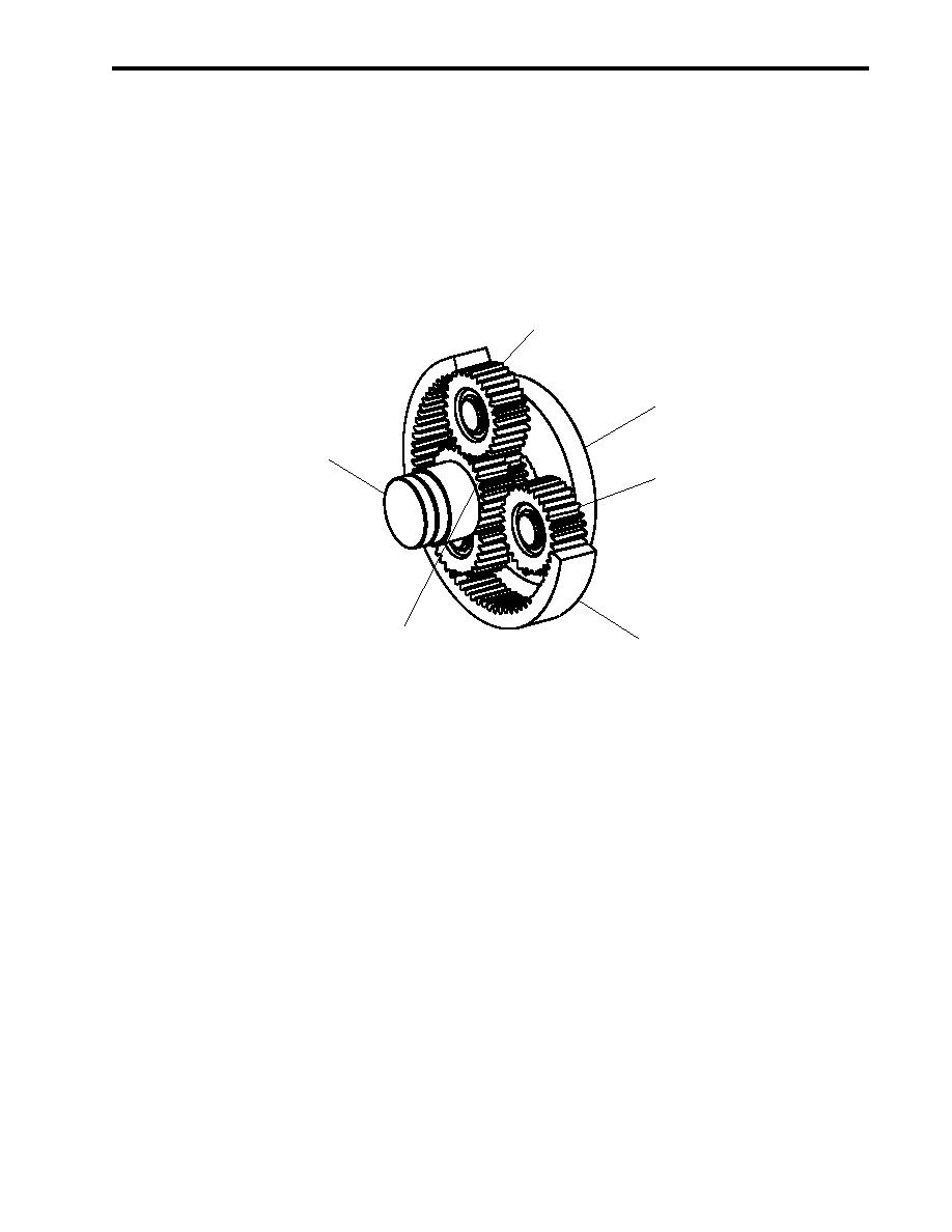
3
5
2
3
1
4
Figure 13. Planetary Reduction Gear Operation
ELECTRICAL OPERATING THEORY
Primary control of the towing machines is from the towing machine control panel (operator) on the 01 level aft. This
operating location places the operator safely away from the towing machines and wire ropes during towing operations. The
local control stations (figure 12, item 9) are provided only for emergency or maintenance operation.
Towing machine main shaft rotation is controlled by the PAYOUT/HEAVE lever (figure 14, item 1). This lever controls a
solenoid-operated valve which, in turn, controls the flow of hydraulic fluid to the hydraulic motor (figure 12, item 1).
Two speed control for the towing machine hydraulic motor (figure 12, item 1) is controlled by the speed control switch
(figure 14, item 2). This switch energizes and deenergizes a solenoid-controlled pilot valve that shifts the hydraulic motor
between low and high speed.
Remote shutdown of the pump drive engine is controlled by the HYDRAULIC PUMP ENGINE SHUTDOWN switch
(figure 14, item 3). When CLOSED, this switch enables pump drive engine operation. When OPEN, the pump drive engine
and central hydraulic power unit are both shut down.
Each towing machine is provided with a CABLE OFF indicator (figure 14, item 4) that also stops the central hydraulic
motors. This indicator receives input from a worm gear-driven sensor (figure 12, item 10). This sensor measures drum
(figure 12, item 3) rotation and converts this rotation into feet of cable payed off. The sensor input is directed though the
0039 00-21
|
||
|
||


