
| Tweet |

Custom Search
|
|

|
||
 TM 55-1925-273-10-1
OPERATOR'S MANUAL
INLAND AND COASTAL LARGE TUG (LT)
DESCRIPTION AND USE OF OPERATOR CONTROLS AND INDICATORS
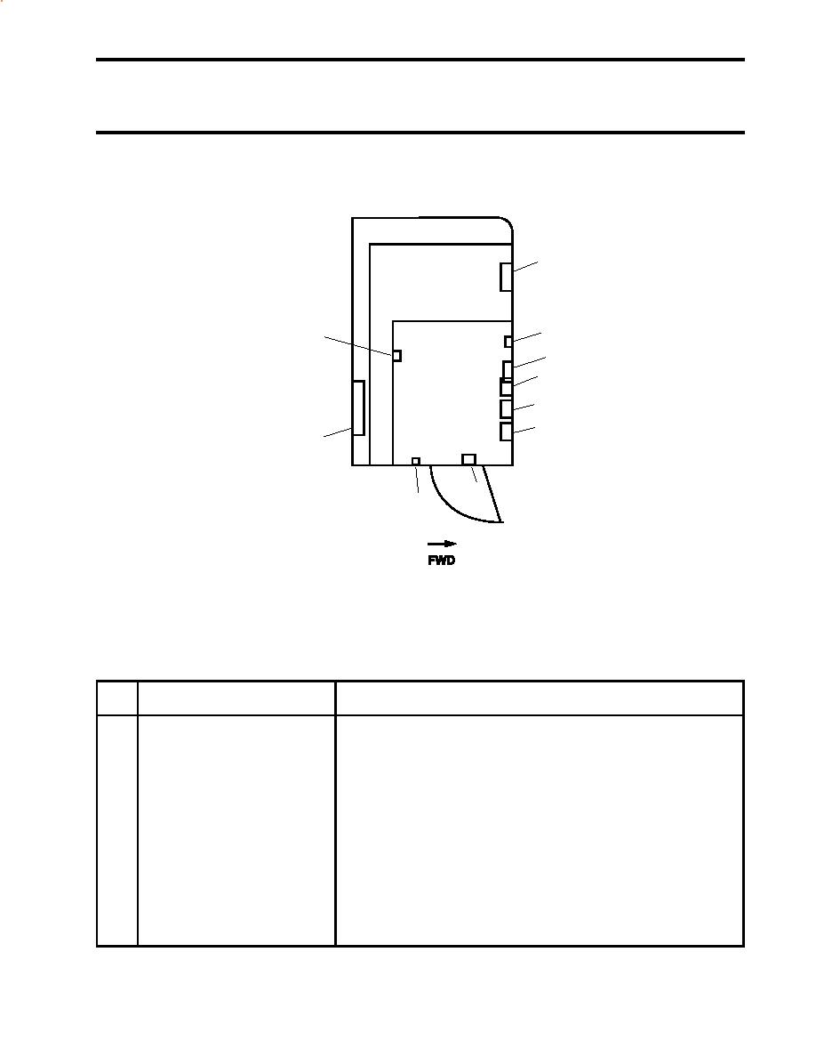
01 LEVEL FAN ROOMS
01 LEVEL FAN ROOM, AFT
1
2
10
3
4
5
6
9
7
8
Figure 1. 01 Level Fan Room, Aft
Table 1. 01 Level Fan Room, Aft (refer to figure 1)
Key
Control/Indicator
Function
1
Power Supply
This unit supplies power to the communications gear in the pilothouse and
radio room. See figure 3 for details.
2
60 Amp Disconnect
This switch turns the power supply ON and OFF. See figure 4 for details.
3
200 Amp Disconnect
This switch turns ON and OFF power from the batteries to the communica-
tion gear. See figure 4 for details.
4
HVAC SYSTEM
This controller turns ON and OFF reheater 01-32-2. See figure 5 for details.
CONTROLLER FOR RHTR
01-32-2
5
HVAC SYSTEM CONTROLLER This controller turns ON and OFF reheater 01-31-2. See figure 5 for details.
FOR RHTR 01-31-2
0061 00-1
|
||
|
||


