| Tweet |

Custom Search
|
|

|
||
 TM 5-1940-277-20
TM 1940-20/2
INSTALL:
1.
Place scoop control head levers (14) in neutral position.
2.
Insert cable (16) into cable fitting and rotate lever (14) one complete revolution away from console. With lever again
in neutral position, approximately two inches of cable will be visible in spent cable tube (IS).
3.
Using 3/4 inch open end wrench install split couplings (10) securing cables.
4.
Place scoop control head (13) in console.
5.
Using screwdriver and 10 mm open end wrench install four screws (11) and nuts (12) securing scoop control
head (13) to console.
6.
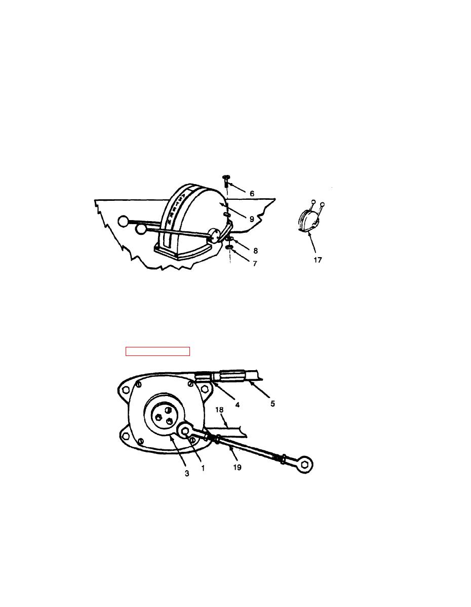
Place scoop control housing (9) over scoop control head.
7.
Using screwdriver and 8 mm open end wrench install four screws (6), washers (8) and nuts (7) securing scoop control
housing (9) to console.
8.
Place scoop control levers (17) in FULL FORWARD position.
9.
Close access panel (refer to paragraph 3-154).
10.
Turn crank (3) to nine o'clock position.
11.
Insert cable end (5) into cable fitting and turn crank (3) to take up slack of cable. Several inches of cable will be visible
in spent cable tube (18).
NOTE
Control rod (19) may be adjusted to slide onto crank.
3-60
|
||
 |
||