| Tweet |

Custom Search
|
|

|
||
 TM 5-1940-277-20
TM 1940-20/2
5.
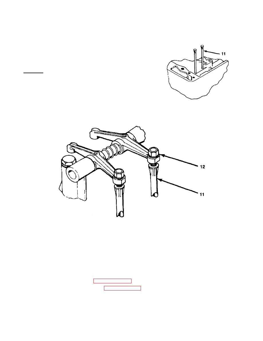
Take out push rods (11) and inspect for warpage, cracks
or breaks. Replace push rods (11) if damage is detected.
6.
Reinstall push rods.
INSTALL
1.
Install bolts (5) through two intermediate rocker arm
supports (6) into tapped holes in shaft (10).
2.
Tighten bolts (5) using 7/16-inch socket.
NOTE
Components must go back on shaft in the same order they came
off.
3.
Install remaining components (2, 6, 7, 8 and 9) in order, using tagged rocker arms as guides, onto
rocker arm shaft (10).
4.
Hold assembly together by the ends and take it to the cylinder head.
5.
As one person holds the assembly (1) in place the other person installs lockwashers (4) and bolts (3)
into end rocker arm supports (2) and into cylinder head making sure that capped ends of push
rods (11) engage adjusting screw (12) in rocker arms.
6.
Using 9/16-inch socket, reinstall remaining five lockwashers (4) and bolts (3) to hold rocker shaft
assembly (1) to cylinder head.
7.
Tighten each bolt in turn 1/2 turn in order to seat assembly evenly as valve spring pressure is taken
up.
8.
Torque all seven bolts (3) to 1722 lb-ft (2329 Nm).
9.
Adjust valve tappets (refer to paragraph 3-128).
10.
Replace rocker arm cover (refer to paragraph 3-125).
11.
Close engine hatch covers.
|
||
 |
||