| Tweet |

Custom Search
|
|

|
||
 TM 5-2805-261-13
The reciprocating power of the pistons is changed to rotary
power by the crankshaft. The crankshaft turns the drive shaft
by means of a splined coupling. The drive shaft extends
through the lower unit to the gear case where a pinion gear fits
on the splined end of the shaft. The pinion gear meshes with
two bevel gears which rotate freely and in opposite directions on
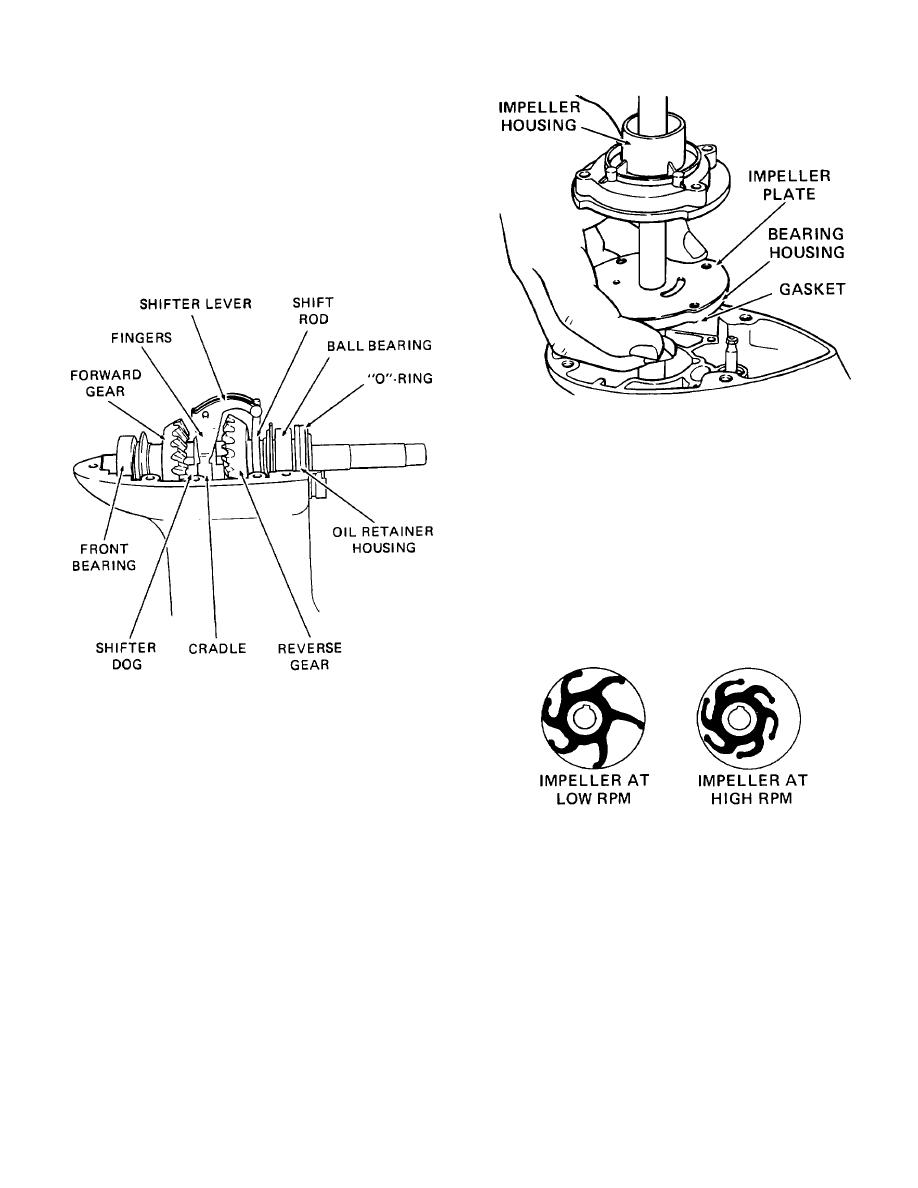
the propeller shaft. A shifter clutch dog is placed between the
clutch dog is shifted by the shifter lever fingers, which in turn
are operated by the manual shift lever through the action of the
shifter rod.
Figure 1-21. Water pump
The impeller housing is offset. This design feature causes the
synthetic rubber blades of the impeller to flex as they rotate,
with the result that the space between the blades varies. The
pump inlet port, in the impeller plate, is open to the impeller
blades when the space between them increases. The pump
outlet port, located in the impeller housing, is open to the blades
when the space between them is decreasing. Consequently, at
low engine RPM the impeller functions as a displacement pump
by drawing water in and then pushing it up the water tube and
through the cooling system channels in the cylinder block. At
high engine RPM water resistance prevents the blades from
touching the side of the housing and the impeller works as a
centrifugal pump.
Figure 1-20. Forward and reverse gears
When the shift rod is in the neutral position, the clutch dog is
centered between the two bevel gears and is not engaged with
either one.
Consequently, the propeller shaft remains
motionless. When the shift rod is in the forward position, the
clutch dog is moved on its splines by the shifter lever into
engagement with the forward bevel gear and the propeller shaft
Figure 1-22. Water pump impeller
is driven clockwise. When the shift rod is in the reverse
position, the clutch dog is moved into engagement with the
1-14. OPERATION OF THE UNIT.
reverse gear and the propeller shaft is driven in a
counterclockwise direction.
The flywheel is rotated initially by pulling the rope on the
manual starter. This action brings the pinion gear on the starter
The water pump consists of an impeller housing, an impeller,
into engagement with the ring gear on the flywheel and turns
an impeller plate and a bearing housing. The impeller is keyed
the flywheel. After the engine has started, the pinion gear falls
to the driveshaft which passes completely through the water
out of mesh with the ring gear.
pump. As the driveshaft turns, so does the impeller.
As the flywheel is turned by the starter, one of the pistons
moves upward in its compression stroke. This creates a partial
vacuum in the crankcase that is lower than the air pressure in
the carburetor throat. Under greater pressure, the leaf valve
opens, allowing the next fuel-air charge to enter the crankcase.
1-11
|
||
 |
||