| Tweet |

Custom Search
|
|

|
||
 TM 5-2805-261-13
LOCATION/ITEM
ACTION
REMARKS
4-15. MANUAL STARTER DISASSEMBLY/CLEANING/I NSPECTION/R EASSEMBLY - continued
NOTE
Lubricate spindle with GAA
grease before installation.
CAUTION
Be sure cup side of friction
ring (14) faces flange on
spindle (12). Flat side of fric-
tion ring must aline with flat
on spindle. Ribs in bushing
(13) must engage corre-
sponding slots in spindle .
14. Spindle (12)
Assemble with spring washer
(15), friction ring (14), and
spindle bushing (13).
15. Spindle assembly
Insert into pulley (7).
NOTE
Pulley may have to be moved
slightly so spindle can drop
over boss in housing.
16. Screw (10) and washer
Install in spindle (12).
(11)
17. Nut (9)
Install.
After installing nut, be sure pulley does not bind.
18. Grommet (18)
Install in starter housing
(17).
19. Pulley (7)
Turn counterclockwise until
tight then back off until rope
knot recess in pulley alines
with rope opening in housing.
Place punch in hole in pulley
to hold assembly in position.
Punch will engage rib in
housing and hold pulley in
place. Do not jar assembly.
20. New rope
Cut a length 6 feet (1.84
meters) of NSN-4020-01-
011-0665 and fuse at each
end with a flame.
NOTE
Ends of rope must be fused
to a length of 1/2 inch
(13mm).
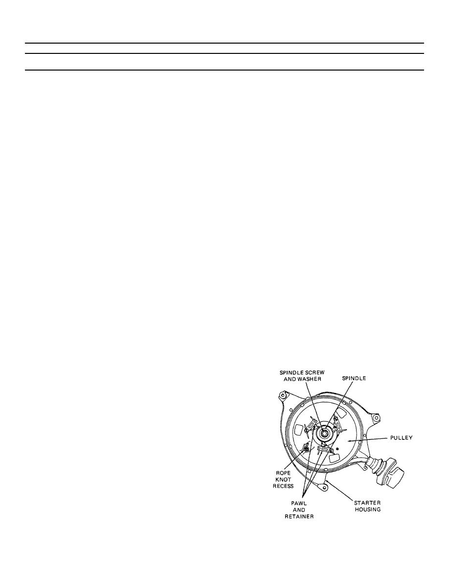
Figure 4-10. View of assembled starter
4-13
|
||
 |
||