| Tweet |

Custom Search
|
|
|
|
||

|
||
 TM 55-1905-217-12
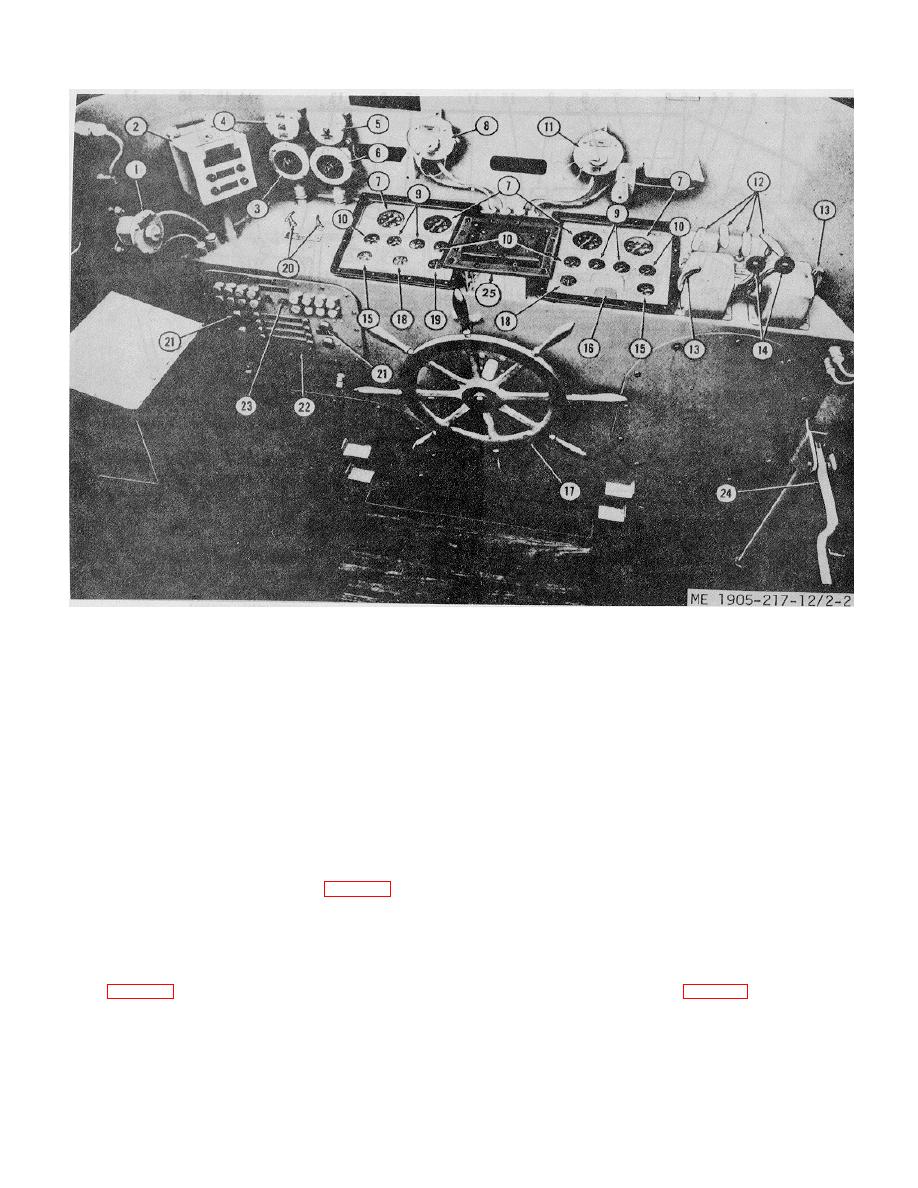
1. Radio receptacle
9. Engine oil pressure
18. Alternator ammeter
2. Engine alarm panel
10. Engine water tempe
19. Battery charge ammeter
3. Rotary switch, naviga-
ture
20. Hydraulic Barter
tional lights
11. Receptacle
controls
4. Toggle switch, naviga-
12. Engine stop control
21. Electric starter controls
tional lights
13. Neutral throttle control
22. Distribution panel
5. Switch, cargo well lights
levers
23. Horn button
6. Rotary switch, panel
14. Engine control levers
24. Ramp hoist control valve
lights
16. Transmission oil pressure
lever
7. Tachometer
16. Rudder angle indicator
25. RHMS heading indicator
8. Compass outlet
17. steering wheel
Figure 2-2. Pilot house control and instruments, hull numbers 8510 thru 8509.
b. Engine Room Controls
the rear of each unit. When the lever is pulled up (pin
disengaged), the lever can be moved independently to
(1) The engine throttle controls (fig. 2-7.1) are
control the individual engine.
separate throttle controls for each engine and are
(3) The shift control for hull numbers 8500
mounted at the rear of the propulsion unit.
through 8518 has a master shift and throttle control
(2) The throttle control of the propulsion unlit on
(fig. 2-7) which provides the same control as the levers in the
hull numbers 8540 through 8560 and 8580 through 8618
pilot house.
(fig. 2-6) is accomplished by pulling, out and rotating the
(4) The shift control (fig. 2-6.1) is used to shift the
pin (16, fig. 2-8.1) on the control 90 degrees. Throttle
transmission. To shift the transmission in the engine
control of each individual engine is accomplished by
room the cable from the pilot house
pulling up on the individual throttle lever mounted on
2-3
|
||
 |
||