| Tweet |

Custom Search
|
|
|
|
||

|
||
 TM 55-1905-217-12
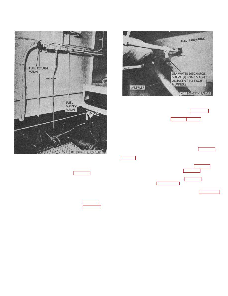
Figure 2-13. Sea water discharge valve.
(5) Move hoist valve lever (fig. 2-35) to
RAMP DOWN.
(
(6) Neutral throttle (fig. 2-31 or 2-32 for hull
numbers 8540 thru 8560 and 8580 thru 8618) may be
used to accelerate raising or lowering ramp.
(7) Move hoist valve lever to NEUTRAL
position when ramp is lowered and cable is slack.
c. Normal Operation to Raise Ramp.
(1) Move ramp control valve lever (fig. 2-36
for hull numbers 8540 thru 8560 and 8580 thru 8618 and
Figure 2-12. Fuel system valves.
(2) When ramp is raised, return lever to
NEUTRAL position and secure load binders (fig. 2-39).
b. Normal Operation to Lower Ramp.
(3) Disengage pump clutch (fig. 2-25).
(1) Ramp hoist valve (fig.
d. Emergency Operation to Lower Ramp.
numbers 8540 thru 8560 and 8580 thru 8618) must be in
(1) Disconnect load binders (fig. 2-39).
neutral position.
(2) Refer to figure 2-26.1 and lower ramp.
(2) On hull numbers 8500 thru 8519 be sure
e. Emergency Operation to Raise Ramp.
the supply valve, located at the bottom of the ramp hoist
(1) Use chain hoists (2) as shown in figure 2-39.
system tank, is open.
Hoists are stored in the lazarette.
(3) With engine running, start hydraulic ramp
(2) Secure load binders.
hoist pump (one only) by engaging clutch (fig. 2-25).
(4) Disconnect load binders (fig. 2-39) at
ramp (both sides).
2-16
|
||
 |
||