| Tweet |

Custom Search
|
|

|
||
 TM 55-190-217-12
(7) Refer to paragraph 4-31 and make injector rack
(2)
Disconnect the drain tube from the fuel
control adjustment.
pump.
(3) Remove the three pump attaching bolt and
seal assemblies, using wrench J4242, and withdraw the
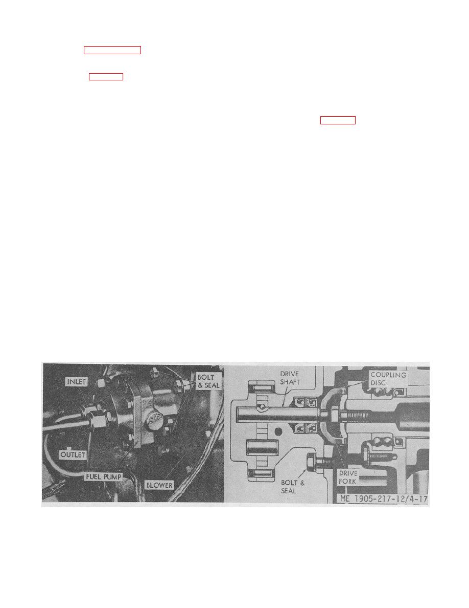
4-29. Fuel Pump (fig. 4-17)
pump from the blower.
a. General.
(4) Check the drive coupling fork, and, if broken
(1) The positive displacement gear-type fuel
or worn, replace it with a new coupling.
pump transfers the fuel from the supply tank to the fuel
injectors. The pump circulates an excess supply of fuel
through the injectors which purges the air from the
used on "B" engines and the right-hand pump is used on
system and cools the injectors. The unused portion of
"D" engines. The pumps are not interchangeable. The
fuel returns to the fuel tank by means of a ,fuel return
pump must always be installed with the inlet opening in
manifold and fuel return line.
the pump cover (marked "LH IN" or "RH IN") on the side
(2) The pump is attached to the rear end plate
toward the cylinder block. Install the pump as follows:
cover of the blower assembly with three bolt and seal
(1) Affix a new gasket to the pump body
assemblies. The seals are flat, soft copper washers
mounting flange and locate the pump drive coupling fork
which prevent the oil in the blower cover from seeping
over the squared end of the drive shaft with prongs of
out around the bolt threads. The pump is driven off the
fork directed away from the pump.
end of the blower lower rotor by means of a drive
(2) Place the fuel pump assembly up against
coupling fork attached to the end of the pump drive shaft
the blower with the prongs of drive coupling fork in
and mating with a drive disc attached to the blower rotor.
registration with slots in drive disc on the blower rotor
(3) Fuel pumps are furnished in left-hand or
shaft.
right-hand rotation, according to the engine model, and
(3) Secure the pump to the )lower, with three
are stamped, "LH IN" or "RH IN". The left hand -pumps
bolt and seal washer assemblies.
are used on LB-RB engines while the right-hand pumps
(4) Connect the inlet and outlet fuel tubes to the
are used on LD-RD engines. These pumps are not
fuel pump.
interchangeable, nor can a pump made for one rotation
(5) Connect the drain tube to the fuel pump
be rebuilt for the other rotation since the relief valve can
body.
be installed in only one position in the pump body.
b. Removal.
4-30. Governor
(1) Disconnect the fuel lines from the inlet and
outlet openings at fuel pump.
a General.
Each governor has an identification plate located on the
control housing, containing the governor assembly
number type-,
Figure 4-17. Fuel pump.
4-22
|
||
 |
||