| Tweet |

Custom Search
|
|

|
||
 TM 55-1905-217-12
8540 thru 8560 and 8580 thru 8618 which incorporate a
fuel pressure switch to prevent accidental engagement of
the hydrostarters when the engine is running.
b. Energy required for hydraulic cranking is
supplied by fluid stored under approximately 3,000 PSI
pressure in two interconnected accumulators. These
accumulators are charged first by a hand operated
hydraulic pump and then by engine driven pumps. They
will not be over-charged during long periods of engine
operation because of pressure control built into the
pumps. There is also a system relief valve set at 3,400
PSI, which is the safe maximum pressure for this
system.
4-58.
Filling the Hydraulic Starting System with
Fluid
a. Servicing. Fill reservoir with suitable hydraulic oil
(Sym. 2135TH or Sym. 2075TH of MIL-L-17672B).
Reservoir capacity is 7 gallons.
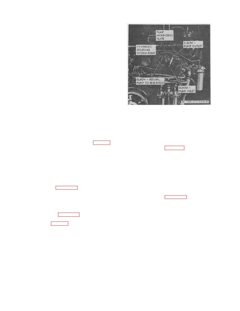
Figure 4-49. Hydraulic starting system pump.
b. Purging.
(1) Hand pump. Loosen discharge
(3) Remove filter from the line connections
connection and operate hand pump slowly until all air is
and remove end cap.
expelled. Retighten connection.
(4) On hull numbers 8540 thru 8560 and 8580
(2) Engine driven pump. With the engine
thru 8618, unscrew the filter outer shell and remove the
running at 1,500 rpm or more, loosen the hose
element.
connection at the discharge side of the pump (fig. 4-49)
until a full stream of oil is discharged. Connect the hose
4-60.
Accumulator (fig. 4-52)
to the pump and alternately loosen and tighten the swivel
fitting on the discharge hose until the oil leaking out,
a. General. Two accumulators are provided, one
when fitting is loose, appears free of air bubbles.
mounted on each side of the engine room. When both
accumulators are at full pressure, one should be secured
4-59.
Filter
(valve closed) and held in reserve. One accumulator will
service both engines under normal conditions.
a. General. On hull numbers 8500 thru 8519 the
b. Accumulator Removal.
filter is mounted near the reservoir on the starboard side
(1) Close valve on opposite accumulator.
of the engine room. See figure 4-50. The same filter is
(2) Release oil pressure in the hydraulic
used on hull numbers 8520 thru 8539 but it is mounted
starting system lines.
below the central deck plate between the two propulsion
(3) Refer to figure 4-52 and remove
unit. The deck plate must be removed to service this
accumulator by removing support clamps.
filter. On hull numbers 8540 thru 8560 and 8580 thru
c. Charging Accumulator with Nitrogen.
8618, a different type filter is mounted on the starboard
(1) Secure accumulator in a pipe vise or a
side of the reservoir. See figure 2-18.
suitable clamp, so that the accumulator is rigid and
stable.
b. Filter service (fig. 4-51). Change the filter every
(2) Using special charging assembly, attach
2000 hours of operation.
gage end of assembly to the nitrogen tank.
(1) Close outlet valve at reservoir (hull
(3) Mount swivel connector on the
numbers 8500 thru 8519).
accumulator air valve. Hand tighten sufficiently to
(2) Relieve pressure in lines on hull numbers
compress gasket in swivel connector to prevent gas
8520 thru 8560 and 8580 thru 8618.
leakage. Loosen locknut on air valve.
(4) Introduce nitrogen gas (50 psi only). DO
NOT EXCEED 50 PSI.
4-55
|
||
 |
||