| Tweet |

Custom Search
|
|

|
||
 TM 55-1905-217-12
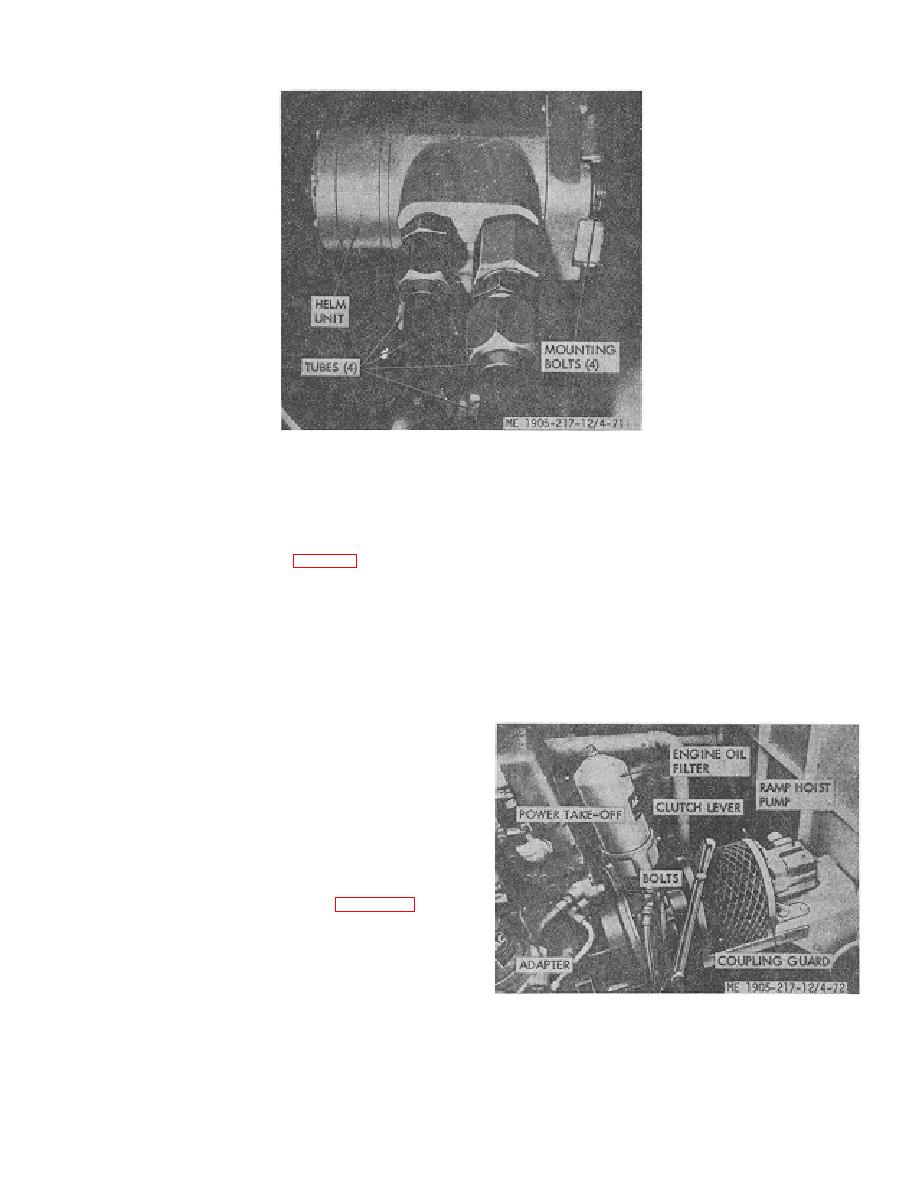
Figure 4-71. Helm unit removal
SECTION XVIII. POWER TAKE-OFF
ing the clutch drive shaft to prevent the clutch from
4-83. General
turning, turn the clutch adjusting ring counterclockwise
The outboard engine of each propulsion unit is equipped
and tighten the clutch until the desired pressure on the
with a front-mounted power take-off (fig. 4-72) to drive the
outer end of the hand lever, or at the clutch release shaft
hydraulic pumps for the ramp hoist system. Each power
is obtained. Then, reinstall the clutch adjusting ring
take-off includes a lever operated clutch. A front end
spring lock, making sure the ends of the lock are in the
power takeoff adapter supports the power take-off
notches in the adjusting ring.
assembly and surrounds the clutch and drive
mechanism. The adapter retains the crankshaft oil seal
e. When the clutch is properly adjusting, the
and is bolted to the engine front end plate and cylinder
approximate pressure required at the outer end of the
block.
hand lever to engage the clutch is 55 lbs.
4-84. Clutch Adjustment
When the clutch is properly adjusted, heavy pressure is
required at the outer end of the hand lever to move the
throw out linkage to the "over-center" or locked position.
Adjust clutch as follows:
a Disengage the clutch.
b Remove the inspection hole cover to expose the
clutch adjusting ring.
c Rotate the clutch, if necessary, to bring the
clutch adjusting ring lock within reach. See figure 4-73.
d Remove the clutch adjusting ring spring lock
screw and lock from the inner clutch pressure plate and
adjusting ring. Then, while hold
Figure 4-72. Power take-off.
4-72
|
||
 |
||