| Tweet |

Custom Search
|
|

|
||
 TM 55-1905-217-12
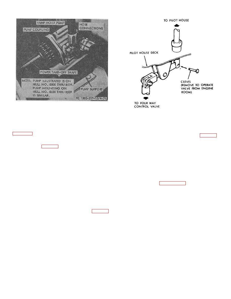
Figure 4-74. Ramp hoist hydraulic pump.
R20BL valve mounted just below the deck in the engine
ME 1905-217-12/4-75
room. The control lever is on the starboard side of the
Figure 4-75. Ramp hoist control valve linkage
pilot house. The control valve used on hull numbers 8540
installation, hull numbers 8540 thru 8560 and 8580 thru
thru 8560 and 8580 thru 8618 incorporates an internal
8618.
relief valve which limits system pressure to 2100 psi. See
4-91. Winch (Hull Numbers 8520 thru 8539 (fig. 4-78))
hull numbers 8540 thru 8560 and 8580 thru 8618.
The winch is located forward on the starboard aside of
the hull. Maximum line pull is 22,000 pounds at 1,900 psi.
b. Removal (fig. 4-76).
The winch consists of a primary drive housing and a final
drive housing fastened to a winch base 'by dowel bolts
(1) Clean hose connections, disconnect, and
which hold the housings concentric. The primary drive
cap open ends. Tag hoses to assure proper
housing contains a hydraulic motor which drives the sun
reconnection.
gear of a primary planetary reduction.
(2) Disconnect operating lever link
(,hull
4-92. Ramp Hoist Pump (Hull Numbers 6520 thru
numbers 8520 thru 8560 and 8580 thru 8618).
8539)
a. General. See figure 2-26.1. The hand pump is
(3)
Remove mounting bolts and remove control
used only for emergency lowering of the ramp. Pressure
valve.
provided by the hand pump will release the winch brake
as controlled by the ball valve
c. Installation. Install control valve in reverse order
of removal.
b. Service. Oil level in the hand pump reservoir
should be approximately 2/8 full.
4-90. Winch (Hull Numbers 8500 thru 8519 (fig. 4-77)
The winch is mounted forward in the port side of the hull.
c.
Removal.
It is rated at 200 psi operating pressure, with a line pull of
14,2.50 pounds and a line speed of 100 feet per minute
(1)
Clean pipe fitting and disconnect oil line.
at the first cable layer (bare drum). Hoist or lower time is
approximately 11 seconds. The winch -is driven by a
(2)
Remove mounting nuts and remove hand
hydraulic motor through a double reduction gear reducer.
pump.
Cable is underwound on the winch.
d. Installation. Install hand pump in reverse order of
removal.
4-76
|
||
 |
||