| Tweet |

Custom Search
|
|

|
||
 TM 55-1905-217-12
(3) Slowly open control valve to fully open
4-96. Counterbalance Valve, Ramp Hoist System
position and check indication on test gage. Pressure
(Hull Numbers 8520 thru 8560 and 8580 thru 8618)
should be no greater than 2,000 psi.
(4) Adjust pressure, if necessary, by rotating
a. General. This valve operates .automatically and
adjusting screw on relief valve. Turn screw in
is designed to create artificial back pressure against the
(clockwise) to increase pressure; turn out
winch motor to prevent the winch from falling
(counterclockwise) to decrease pressure.
unrestricted. The relief should be set at 2,100 psi.
(5) Close shutoff valve at test gage to prevent
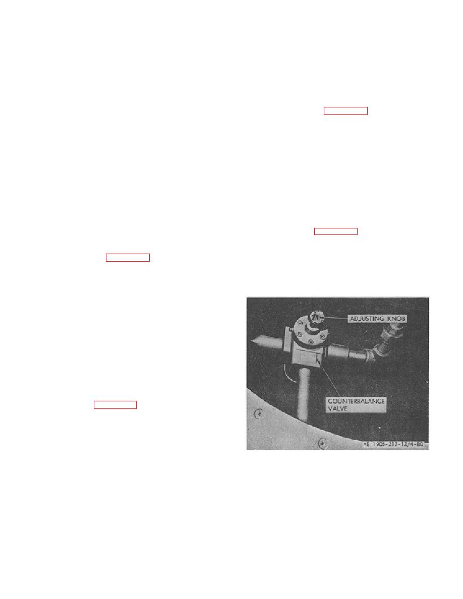
b. Adjustment. See figure 4-80 for counterbalance
rapid and sudden pressure changes from damaging
valve location. Be certain that the relief is set at 2,100
gage.
psi by performing the following:
c. Removal.
(1) Disconnect cable from winch to remove
(1) Clean hose connections, disconnect hoses
load from system.
from relief valve, and cap open ends.
(2) Install 3,000 psi pressure gage, with shut
(2) Remove relief valve.
off valve, in system at tee fitting or port in counterbalance
d. Installation. Install relief valve in reverse order of
valve.
removal.
(3) Place control valve in position for lowering
pump.
4-94. Counterbalance Valve, Ramp Hoist System
(4) Adjust knob on top of valve until system
(Hull Numbers 8500 thru 8519)
pressure is 2,100 psi. A pilot pressure of 2,100 psi will
a. General. This bypass and check valve is used
open the counterbalance valve and allow the ramp to be
lowered.
as an adjustable pressure bypass valve to maintain
sufficient pressure -in the pump circuit for operation of
in the hull near the winch.
the winch brake. It ensures positive control of ramp
(1) Clean pipe connections, disconnect pipe
lowering.
b. Adjustment. See figure 4-77 for counterbalance
from valve, and cap open ends.
(2) Remove valve.
valve location. Set counterbalance valve at 300 psi as
c. Installation. Install valve in reverse order of
follows:
removal.
(1) Disconnect cable from winch to remove
load from system.
(2) Install 3,000 psi pressure gage, with shutoff
valve, in system at tee fitting or port in counterbalance
valve.
(3) Place control valve in position for lowering
pump.
(4) Adjust knob on top of valve until system
pressure is 300 psi. A pilot pressure of 800 psi will open
the counterbalance valve and allow the ramp to be
lowered.
4-95. Winch Brake Valve (Hull Numbers 8500 thru
8519)
identification. This is a spool-type, pressure-operated
valve which directs hydraulic fluid to the brake release
cylinder whenever pressure is applied to either port.
b. Removal.
(1) Clean tube connections, disconnect tubes
from valve, and cap open ends.
Figure 4-80. Counterbalance valve, ramp hoist system
(2) Remove valve from winch.
hull numbers 8520 thru 8560 and 8580 thru 8618.
c. Installation. Install brake valve, in reverse order
of removal.
4-78
|
||
 |
||