| Tweet |

Custom Search
|
|

|
||
 TM 55-1905-217-34
approximately 10 inches long through the selector valve opening in the housing and rest against the plug. Tap the end of
the steel rod with a hammer and drive the plug out of the housing.
(9) Remove the valve seat (38, fig. 3-36), spring (39), cotter pin (40), pressure regulating valve (41) and body (42)
from the control valve.
NOTE
The pressure regulating valve components apply to Rohr Hulls only.
(10) Remove the oil passage covers and gaskets from the sides and top of the control valve housing.
c. Cleaning, Inspection, and Repair.
(1) Wash all parts of the control valve with cleaning solvent (FED. SPEC. PD-680) and dry thoroughly. Be sure to
clean all oil passages with compressed air.
(2) Examine the oil seals, and if the lip of the oil seal is rough or charred, replace the oil seals.
(3) Examine the outer surfaces of the selector valve and shutoff valves for roughness and score marks; also, check
the selector valve poppet seat in the selector valve and the shutoff locating screw ball seat in the shutoff valves for wear. If
the selector valve and poppet seat, or the shutoff valves and locating screw ball seats are worn or scored, replace the
selector valve, shutoff valves and control valve housing.
NOTE
The selector valve, shutoff valves and control valve housing are not serviced separately.
(4) If the selector valve poppet or the shutoff locating screw balls are worn or scored, replace.
(5) Remove all traces of old gaskets from the control valve housing, oil hole covers on twin units and flanges of oil
tube assemblies.
d. Reassembly.
(1) Install the shutoff valve (6) in the control valve housing as follows:
(a) Place the control valve housing (9) on the work bench with the top of the housing facing up.
NOTE
The right-hand and left-hand shutoff valves must be assembled in the correct bores in the control valve
housing; therefore, viewing the control valve housing from the end, the right-hand shutoff valve must
be assembled into the upper right-hand opening in the housing and the left-hand shutoff valve into the
upper left-hand opening in the housing. Right-hand and left-hand shutoff valves may be identified
from the two end views of the valves shown in the inset of figure 3-36.
(b) Lubricate the shutoff valve (6) with engine oil. Then, start the shutoff valve straight into the bore of the housing
with the locating screw slot in alignment with the locating screw hole in the side of the housing. Continue to slide the
shutoff valve in the housing until the slot in the valve is in line with the locating screw hole.
(c) Place a copper washer over the end of the shut off locating screw (20). Then, install the screw in the control
valve housing with the steel ball in the end screw registering with the slot in the shutoff valve. Tighten the screw to 35-39
ft-lb torque.
(d) Stand the control valve housing in a vertical position with the outer end of the shutoff valve facing up.
(e) Apply a thin coat of sealing compound to the outside diameter of the oil seal (3).
(f) Place the shutoff valve oil seal (30) over the end of the shutoff valve with the lip of the oil seal facing the
housing. Then, start the oil seal straight into the control valve housing.
CAUTION
Care should be used not to damage the lip when installing the oil seal over the end
of the shutoff valve.
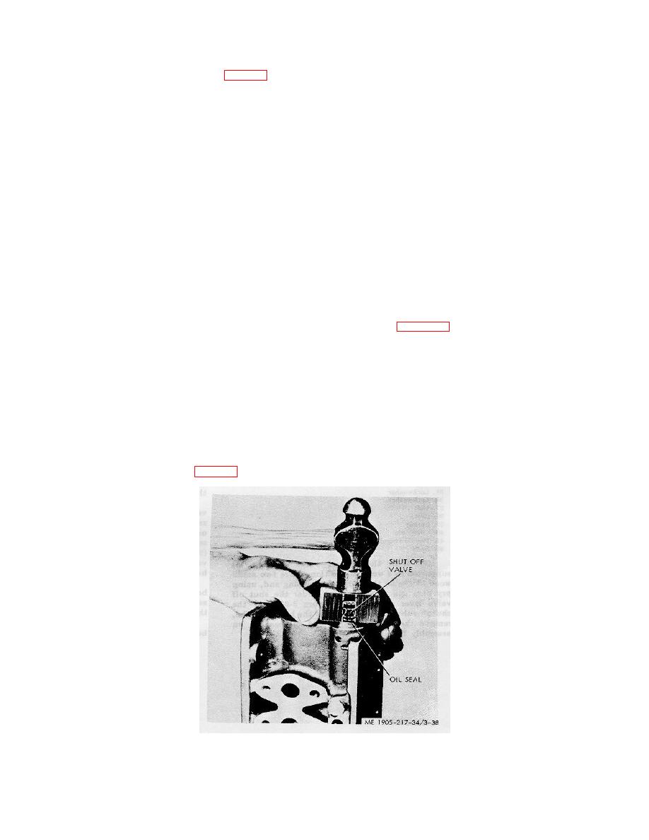
(g) Place a small wood block 1 inch thick with a /2 inch hole drilled through its center over the end of the shutoff
valve and against the oil seal, (fig. 3-38). Then, tap the oil seal straight into the housing until it is flush with the outside
face of the housing.
Figure 3-38. Installing shutoff valve oil seal in control valve housing.
(2) Install the selector valve in the control valve housing as follows:
(a) Lubricate the selector valve with engine
3-54
|
||
 |
||