| Tweet |

Custom Search
|
|

|
||
 TM 55-1905-217-34
Key to figure 3-45
17. Gasket
1. Valve spring locks
18. Gasket
2. Retainer
19. Plug
3. Spring
20. Plug
4. Washer
21. Plug
5. Valve, poppet
22. Tube, injector hole
6. Screw
23. Performed packing
7. Lockwasher
24. Plug pipe
8. Guide, cam follower
25. Valve guide
9. Screw
26. Valve seat insert
10. Lockwasher
27. Nozzle, water
11. Cover, governor
28. Nozzle, water
12. Gasket
29. Connector, Fuel line
13. Plug, pipe
30. Flat washer
14. Gasket
31. Stud, manifold
15. Gasket
32 Stud, exhaust manifold
16. Washer
(8) Remove the screws (6), lockwashers (7), and cam follower guides (8) from the head.
(9) Remove the screws (9), lockwashers (10), governor covers (11), and gaskets (12).
(10) Remove the pipe plugs (13), oil ring gaskets (14), water hole gaskets (15), nonmetallic washers (16),
compression gaskets (17), and water gaskets (18) from the head.
(11) Remove the slotted head machine plugs (19, 20, 21), injector hole tube (22), preformed packing (23), and
pipe plug (24) from head.
(12) Remove the valve guides (25) and valve seat inserts (26).
(13) Remove the water nozzles (27 and 28), fuel line connectors (29), flat washers (30), and studs (31 and 32)
from the head.
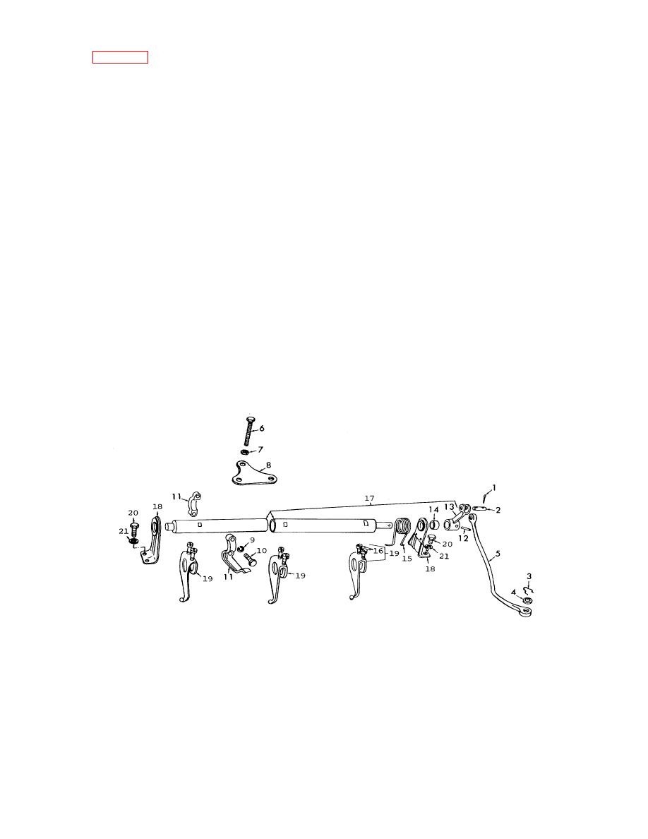
(14) Remove the cotter pins (1, fig. 3-46), straight headless pin (2), retainer (3), flat washers (4), and remove
the governor control links (5).
1. Cotter pin
12. Pin, grooved
2. Pin, straight headless
13. Arm lever
3. Retainer
14. Sleeve spacer
4. Flat washer
15. Spring
5. Link, governor control
16. Screw
6. Bolt
17. Injector control tube
7. Nut, adjusting
18. Support bracket
8. Plate, injector
19. Lever
9. Lock washer
20. Capscrew
10. Capscrew
21.Lockwasher
11. Injector arm
Figure 3.46. Injector control tube assembly, disassembly and reassembly
Change 1 3-65
|
||
 |
||