| Tweet |

Custom Search
|
|

|
||
 TM 55-1905-217-34
(15) Remove the load limit bolts (6), adjusting nuts (7), and injector plates (8).
(16) Remove capscrews (20), lockwashers (21) and remove injector control tube assembly.
(17) Remove the capscrews (9), lockwashers (10) and injector arms (11) from the control tube.
(18) Remove the grooved pins (12) and remove arm lever (13). Remove sleeve spacers (14) from the arm levers.
Remove the springs (15).
(19) Loosen lever screws (16) and remove control tube (17) from levers. Remove levers (19) from rack.
c. Cleaning. After the cylinder head has been stripped of all its component parts and all of the plugs have been
removed, steam clean the head thoroughly. If the water passages have been heavily scaled, remove the copper injector
tubes and water nozzles and clean the cylinder head as follows:
(1) Scrape all gasket material from the cylinder head.
(2) If a core hole plug is difficult to remove, hold a 3/4 inch drift against the plug and give it a few sharp blows with
a one-pound hammer. With a 1/2 inch flexible handle and a short extension place in the countersunk hole in the plug, turn
the plug slightly in the direction of tightening. Then, turn it in the opposite direction and back the plug out.
(3) Remove the grease by agitating the cylinder head in a hot bath of heavy-duty alkaline solution.
(4) Wash the block in hot water or steam clean it to remove the alkaline solution.
(5) If the water jackets are heavily scaled, proceed as follows:
(a) Agitate the head in a bath of inhibited commercial pickling acid.
(b) Allow the head to remain in the acid bath until the bubblingaction stops (approximately 30 minutes).
(c) Lift the head, drain it, and reimmerse it in the same acid solution for 10 minutes.
(d) Repeat step "c" until all scale is removed.
(e) Rinse the head in clear hot water to remove the acid solution.
(f) Neutralize the acid that may cling to the casting by immersing the head in an alkaline bath.
(g) Wash the head in clean water or steam clean it.
(6) Make certain that all water passages and oil galleries have been thoroughly cleaned.
NOTE
The above cleaning procedure may be used on all ordinary cast iron and steel parts of the
engine. Mention will be made of special cleaning procedures whenever necessary.
(7) After cleaning, dry the cylinder head with compressed air.
d. Inspection and Repair. Over a prolonged period of operation, the cylinder head may assume a contour to match that of
the cylinder block, which is normal. However, if the cylinder head is allowed to become overheated because of coolant
loss, the resultant high temperatures cause stresses to occur in the casting which will affect the flatness of the head.
Therefore, check the bottom (fire deck) of the cylinder head for flatness as follows:
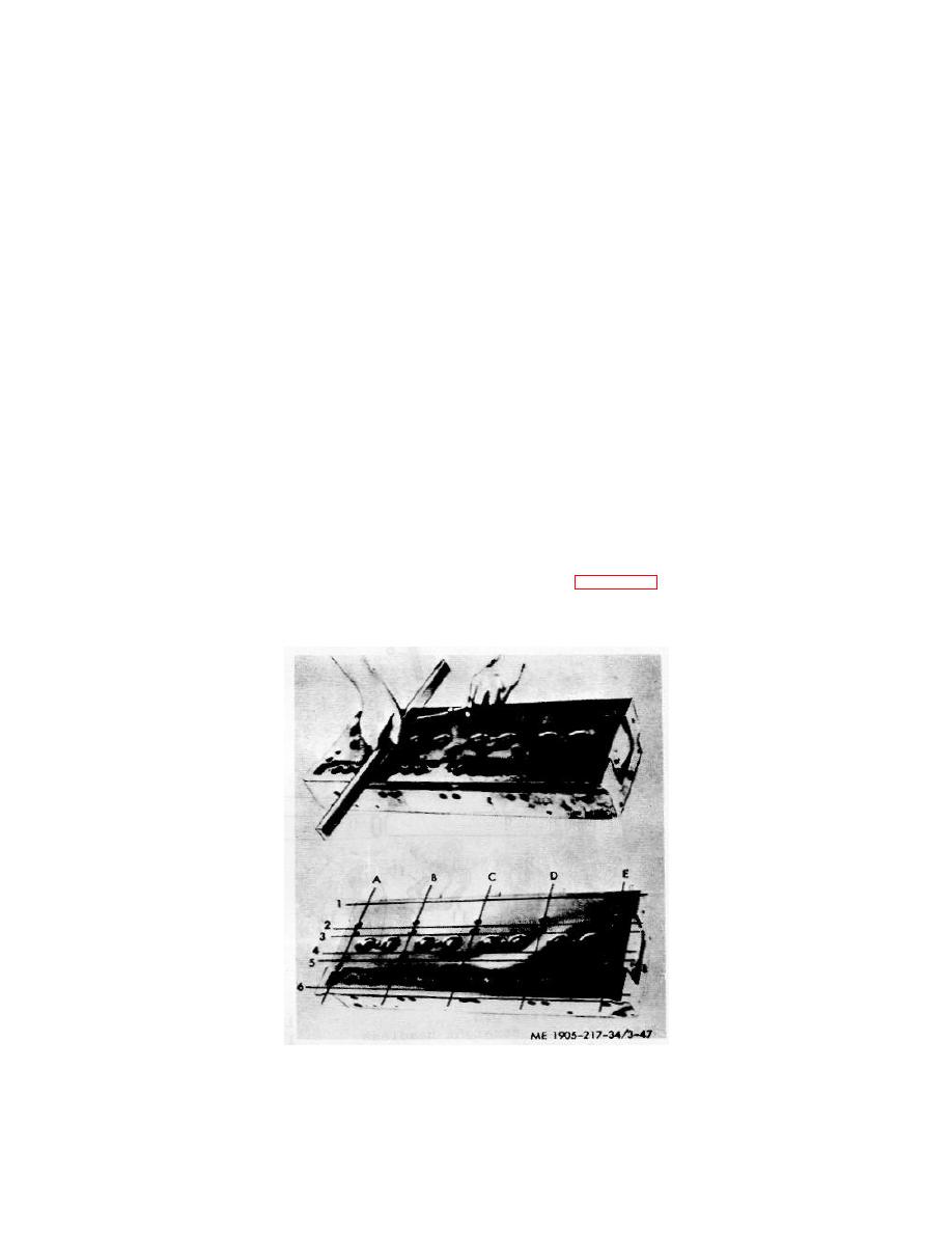
(1) Use a heavy, accurate straight-edge and feeler gage to check for transverse warpage at each end and between all
cylinders. Also, check for longitudinal warpage in six places as shown in figure 3-47. Maximum allowable warpage is
given by the following:
Maximum Longitudinal
Maximum Transverse
Warpage
Warpage
.010 inch
.004 inch
Figure 3-47. Checking bottom face of cylinder head.
(2) Use the maximum allowable warpage limits as a guide in determining the advisability of reinstalling the head
on the engine or of refacing it. The number of times a cylinder head may be refaced will, of course, depend upon the
amount of stock removed from the head during previous reworking operations.
3-66
|
||
 |
||