| Tweet |

Custom Search
|
|

|
||
 TM 55-1905-217-34
(2) Remove locking nut (1) and washer (2) from the shaft.
(3) Pull the alternator from the pulley using a slight rocking motion to free the pulley.
(4) Remove fan (4) from shaft.
(5) Remove two self-tapping screws (60) and remove the rear cover (59) and cover gasket (58).
(6) Remove hex nut (64), lockwasher (63), flat washer (62), and insulator washer (61) from brush cover.
Remove bolt (54), brush connecting lead (55), flat washer (56), and square insulator (57).
(7) Remove brush lead attaching screws (43). Retain cover plate lead.
(8) Remove self-tapping screws (45) securing brush and capacitor assembly (42, 44) and remove
assembly.
(9) Remove through bolts (37) and lockwashers (33).
(10) Using wooden wedge and screwdriver, pry the front and rear sections apart. When apart, the rear
section should contain the stator (20) and the front section should contain the rotor (15).
g. Disassembly of Rear Housing Assembly (Hulls 8540-8560 and 8580-8618).
(1) Separate the stator from the rear section by removing plastic caps (53), hex nuts (52), lockwashers
(51), insulating washers (50), and flat washers (49) from the three AC terminals. Remove stator leads and pull
the stator assembly from the rear section.
(2) Remove hex nuts (48), insulator washers (47), and flat washers (46) securing the alternator terminal
stud. Remove RFI filter. Remove bolts (27), lockwashers (28), and insulator washers (29).
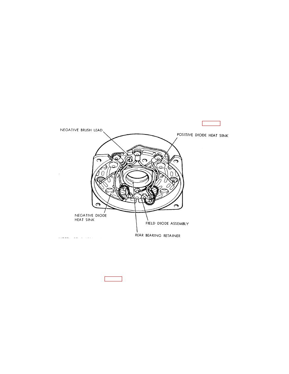
(3) Remove negative brush connector lead from negative rectifier heat sink (fig. 4-3).
Figure 4-3. Diode installation (hulls 8540-8560 and 8580-8618).
(4) Remove hex nuts (41) and washers from bolts (21, 32).
(5) Carefully remove the negative heat sink (31) and the positive heat sink (25) from the rear section.
(6) Separate field diode assembly (22) from the positive and negative heat sinks by pulling bolts (21)
from assembly observing location of molded washer (26) and square insulator (23). Separate heat sinks by
removing harness assemblies (30) from bolts (32).
h. Disassembly of Front Housing Assembly (Hulls 8540-8560 and 8580-8618).
(1) Remove Woodruff key (14, fig. 4-2), flat washer (5), felt washer (6), and the pulley spacer (7).
(2) Remove the retaining screws (8).
(3) Press the rotor (15) from the front housing (9) using an arbor press.
(4) Remove the bearing seal (10) by placing a flat face punch through opening in the housing and
tapping seal.
4-6
|
||
 |
||