| Tweet |

Custom Search
|
|

|
||
 TM 55-1905-220-14-5
3-91.3. IDLER GEAR AND BEARING ASSEMBLY - MAINTENANCE
INSTRUCTIONS (Cont).
LOCATION
ITEM
ACTION
REMARKS
PRE-LOAD CHECK OF BEARING (Cont)
(2) Attach the other plate to the idler gear with three 3/8"-16 bolts. Tighten the bolts to 25-40 lb-ft (37.2-
59.5 kg/m) torque.
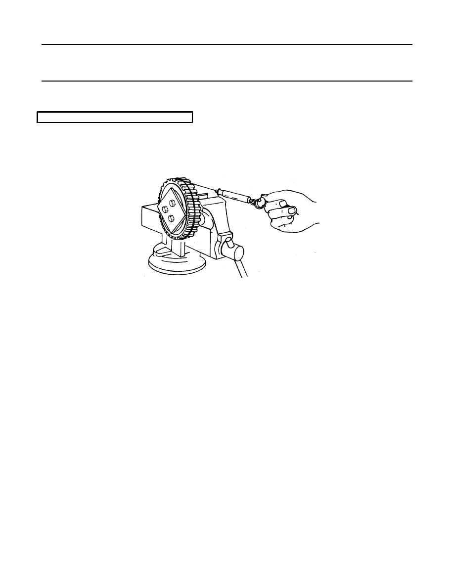
(3) Clamp the idler gear assembly and fixture in vise as shown.
(4) Attach the cord to the idler gear and spring scale and check the pre-load as outlined in item 4 of the
first method.
j.
If the scale reading is within the specified 1 1/4 to 6 lbs., but fluctuates more than the permissible 2 lbs.
11 ounces (12 N), the idler gear and bearing assembly must NOT be installed on the engine. Fluctuations in
scale reading may be caused by the races not being concentric to each other, damaged races or rollers, or dirt
or foreign material within the bearings. In these cases, the bearing should be inspected for the cause of
fluctuation in the scale readings and corrected or a new bearing installed.
k.
A scale reading which exceeds the specified maximum indicates binding of the bearing rollers, or rollers
improperly installed. When the scale reading is less than the specified minimum, the bearing is more likely
worn and should be replaced.
l.
After the pre-load test is completed, remove the steel plates and attach bearing retainer as follows:
(1) Attach the bearing retainer (8) to the idler gear (13) with six screws (6) and locks (7). Tighten the
screws to 24-29 lb-ft (35.7 - 43.2 kg/m) torque.
(2) Bend the ears of each bolt lock against the flat side of the attaching screw heads to secure the
bolts.
3-1564
|
||
 |
||