| Tweet |

Custom Search
|
|

|
||
 TM 55-1905-220-14-6
3-137. HYDRAULIC TANK ASSEMBLY - MAINTENANCE INSTRUCTIONS.
LOCATION
ITEM
ACTION
REMARKS
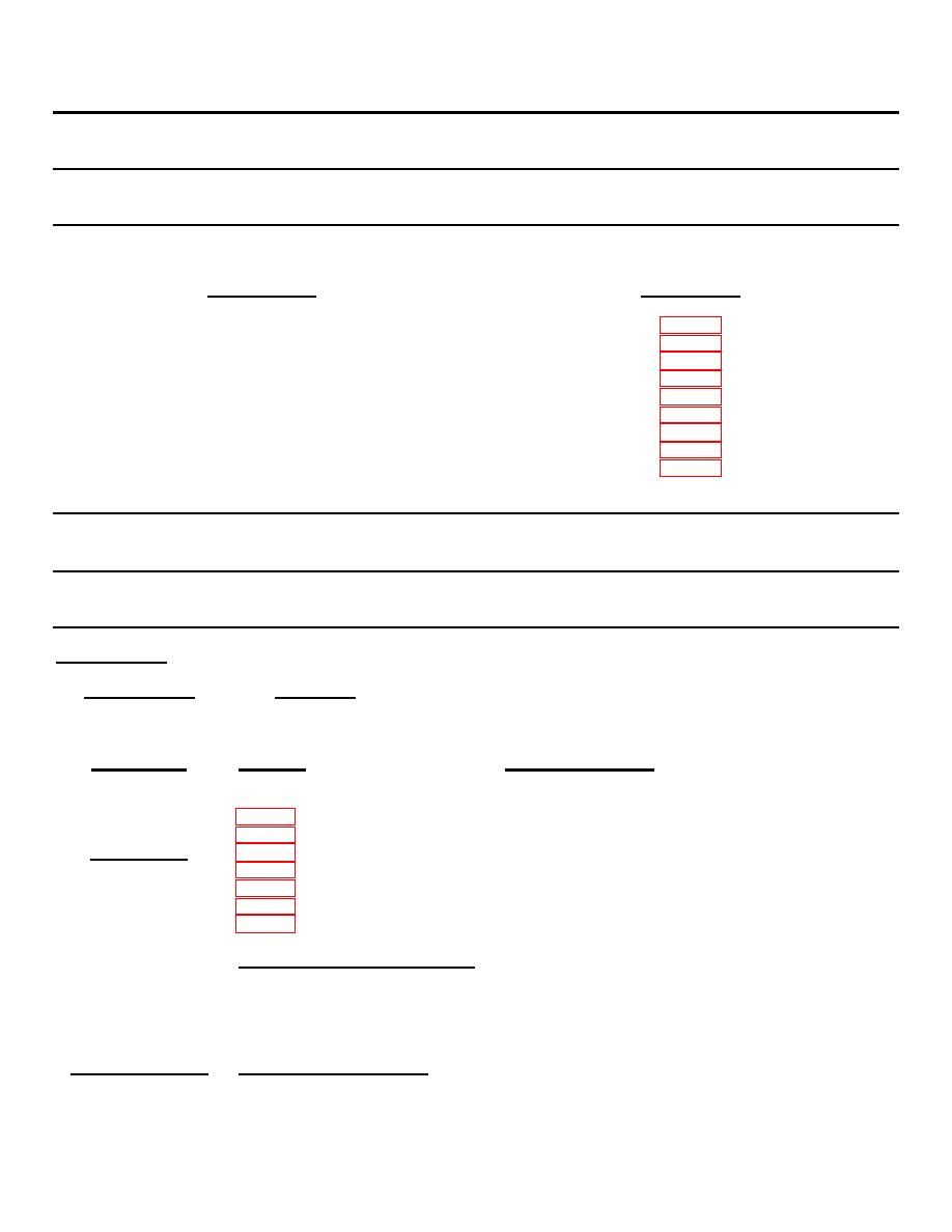
The hydraulic tank assembly maintenance instructions are contained in the following paragraphs:
DESCRIPTION
PARAGRAPH
Tank Assembly
Hydraulic Filter
Pilot Valve and Manifold
Pressure Control Valve
Check Valve
Directional Valve - Pilot Operated
Relief Valve
Pressure Reducing Valve
Directional Valve - Spring Centered Solenoid
3-137.1. HYDRAULIC TANK ASSEMBLY - MAINTENANCE INSTRUCTIONS.
This task covers:
a. Inspection
b. Service
c. Repair
INITIAL SETUP
Test Equipment
References
None
None
Equipment
Special Tools
Condition
Condition Description
Paragraph
Flairing tool
Hydraulic Filter Removal
Pilot Valve and Manifold Removal
Material/Parts
Pressure Control Valve Removal
Check Valves Removal
Lubricating oil
Directional Valve Removal
MIL-L-17672
Relief Valve Removal
Type 2110th
Pressure Reducing Valve Removal
(55 gal)
(208.18 liters)
Special Environmental Conditions
Cover gasket
(P/N 83-7978)
Do not drain oil into bilges.
Use the oil/water separation and
recovery system to collect used oil.
Personnel Required
General Safety Instructions
1
Observe WARNING in procedure.
3-2184
|
||
 |
||