| Tweet |

Custom Search
|
|

|
||
 TM 55-1905-221-14-3
6-18.
ALTERNATOR (Continued).
LOCATION/ITEM
ACTION
REMARKS
TESTING
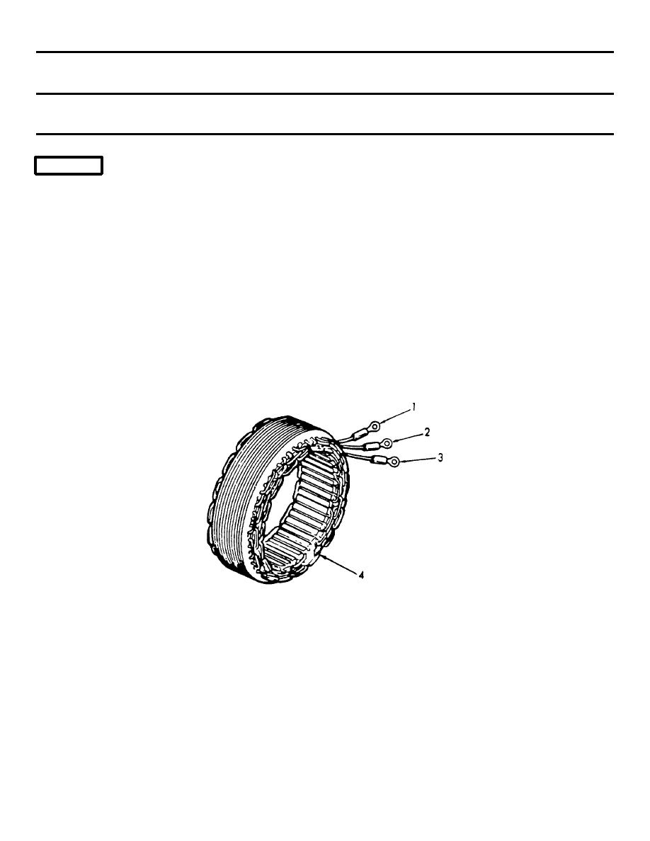
3. Stator
Assembly
NOTE
Perform tests on electrical components using a suitable ohmmeter or multimeter
as follows:
Check for short circuit between
each stator lead and frame. Con-
nect ohmmeter between each stator
lead (1, 2, or 3), and stator
frame (4) in turn. Ohmmeter
should indicate open circuit or
very high resistance. Stator
assembly shall be replaced if
winding(s) are shorted (no or
low resistance).
4.
Brush Assembly
Refer to paragraph 5-12.1 for
and Rotor
testing.
Assembly
5. Rectifier
a. Check resistance of isolation
diodes with ohmmeter. Each
diode should indicate a high
resistance in one direction
and low resistance in other
direction (ohmmeter leads
reversed). Replace defective
isolation diode(s).
6-208
|
||
 |
||