
| Tweet |

Custom Search
|
|

|
||
 TM 55-1905-221-14-4
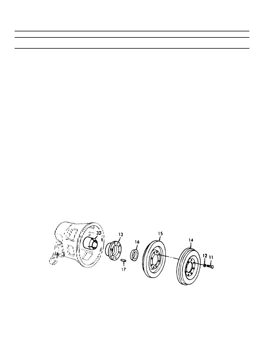
6-41. POWER TAKE OFF COUPLING AND VIBRATION DAMPER (Continued).
LOCATION/ITEM
ACTION
REMARKS
INSTALLATION (Cont)
m. If the light and heavy vibra-
tion dampers (14) and (15)
were removed from the hub
(13), assemble the two dampers
over the dowels (17) and
against the hub with the flat
faces of the dampers facing
each other, then install the
bolts (11) and lockwashers
(12). Tighten the bolts to
57-61 lb-ft (77.3-82.7 Nm)
n. Place the vibration dampers
and hub assembly over the end
of the crankshaft, long end
of hub facing rear cone, and
against the taper on the rear
cone (33).
o. Place the front cone (16) over
the end of the crankshaft with
the tapered end of the cone
facing the hub. Insert the
blade of a screw driver in the
slot in the cone to expand it.
Then slide the cone straight
forward until the taper on the
cone contacts the taper on the
damper hub. Remove the screw
driver.
6-938
|
||
|
||


