| Tweet |

Custom Search
|
|

|
||
 TM 55-1905-222-14
6-12
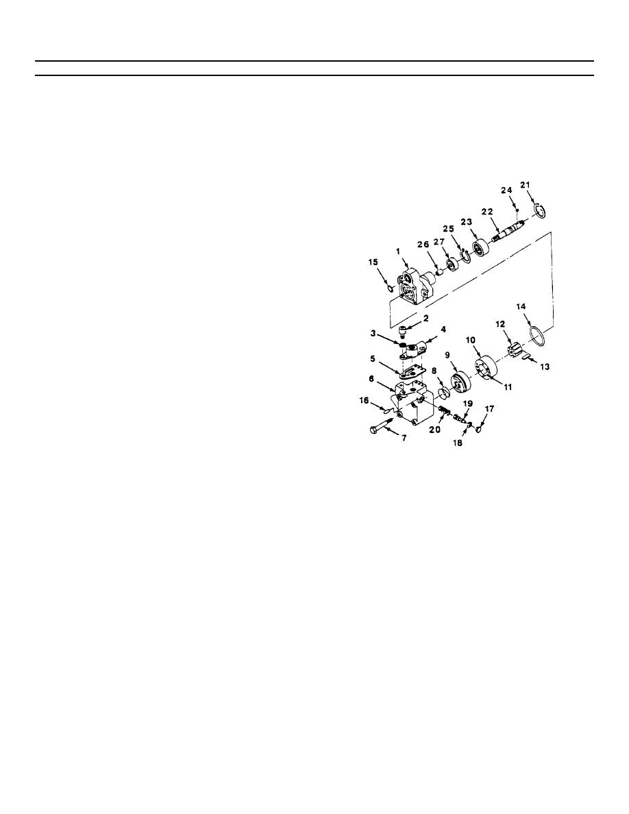
REPAIR STEERING PUMP (Continue(d).
e.
Slide the shaft assembly (22, 24 and 25) into
the body (1).
f.
Install large retaining ring (21) into retaining ring
groove of the body (1).
g.
Insert Woodruff key (24) into the shaft (22).
Tap in place with a small hammer to seat the
key.
h.
Install body (1) mounting flange into a bench
vise with shaft end down. Install 'O' rings (15
and 14) into grooves.
i.
Insert vanes (13) into rotor (12) with radius
edge toward the cam ring (10). Place the rotor
(12) and vanes (13) on top of the body (1) with
the rotor counterbore toward the body.
j.
Insert pins (11) through cam ring (10) and place
the cam ring over rotor (12) and vanes (13).
Check the model code for direction of rotation
and position arrow on the cam ring to agree with
model code (R - clockwise, L - counterclockwise
as viewed from the shaft end).
k.
Install pressure plate (9) over pins (11) and up
against the cam ring (10), rotor (12) and vanes
(13).
I.
Place spring (8) on top of pressure plate (9),
then install cover (6) over spring (8).
m.
Line up cover screw holes with body (1), thread
four screws (7) through cover (6) and into body
(1). Torque screws (7) to 25-30 lb ft.
n.
Insert spring (20) into control valve bore of
cover (6).
6-67
|
||
 |
||