| Tweet |

Custom Search
|
|

|
||
 TM 55-1905-223.-10
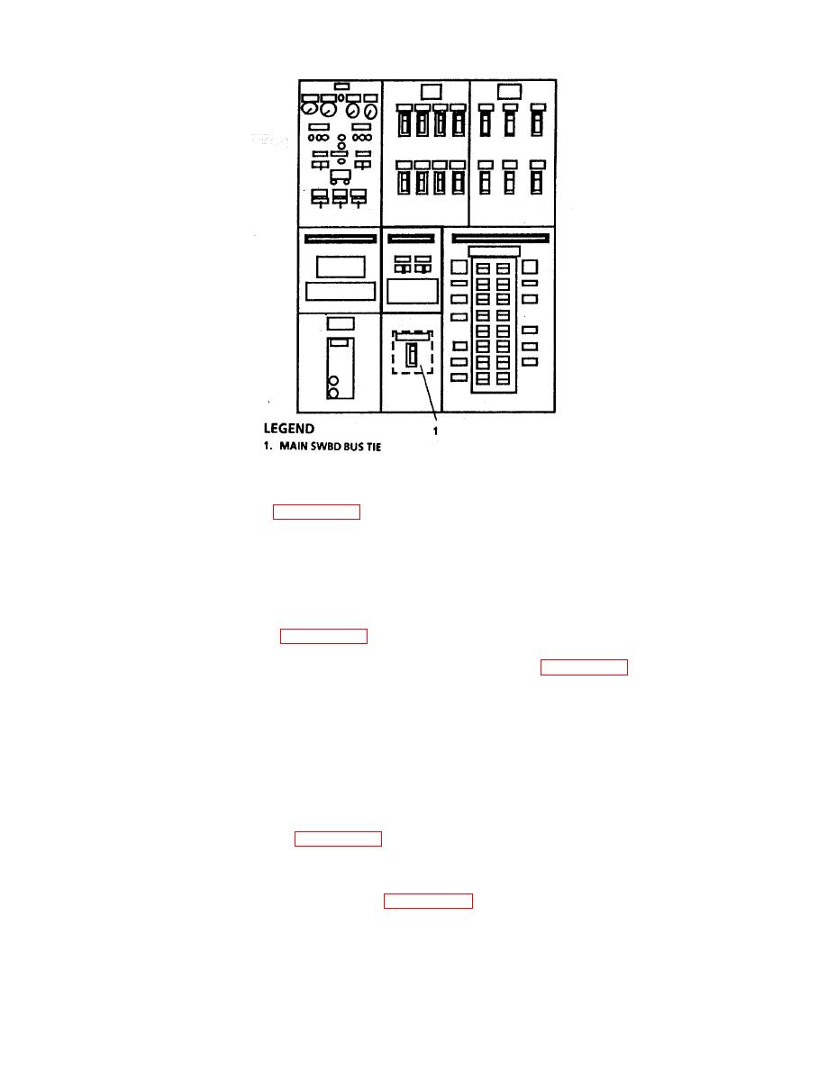
(7) On Main Switchboard (FIGURE 2-95), set circuit breaker (8) to ON position.
(8) On Lighting Panel L102, set circuit breaker 13 to ON position.
(9) At Power Panel P203, set all circuit breakers to ON position.
(10) At Power Panel P204, set all circuit breakers to ON position.
(11) On Main Switchboard (FIGURE 2-95), set circuit breakers (1, 2, and 16) to ON position.
(12) In Engine Room Operating Station, open Engine Efficiency Panel (FIGURE 2-97), set MAIN
POWER switch (1) to UP position, set FIELD POWER switch (4) to DOWN position, and PRIMARY-
BACKUP switch (3) to PRIMARY position.
CAUTION
Ensure FIELD POWER switch (4) is OFF (DOWN) until after monitor system
performs its self check. This allows the battery to be charged.
(13) Set FIELD POWER switch (4) to UP position.
(14) On printed circuit board (FIGURE 2-97), set RUN-BACKUP switch (2) to BACKUP position.
NOTE
Machinery Plant Monitor Panel (FIGURE 2-98) controls are located under panel in
bottom third of monitor.
2-303
|
||
 |
||